Collimator, detection device with collimator, and scanning equipment

A detection device and collimator technology, applied in the field of nuclear medical imaging, can solve problems such as machine damage and inconvenient replacement of collimators

Active Publication Date: 2016-06-29
WUHAN ZHIWEI TECH CO LTD
View PDF8 Cites 9 Cited by
  • Summary
  • Abstract
  • Description
  • Claims
  • Application Information

AI Technical Summary

Problems solved by technology

Because the collimator is large and heavy, it is inconvenient to replace the collim

Method used


Image

  • Collimator, detection device with collimator, and scanning equipment
  • Collimator, detection device with collimator, and scanning equipment
  • Collimator, detection device with collimator, and scanning equipment

Examples


Embodiment Construction

[0042] In order to facilitate a better understanding of the purpose, technical features and effects of the present invention, the present invention will now be further explained with reference to the accompanying drawings and specific embodiments.

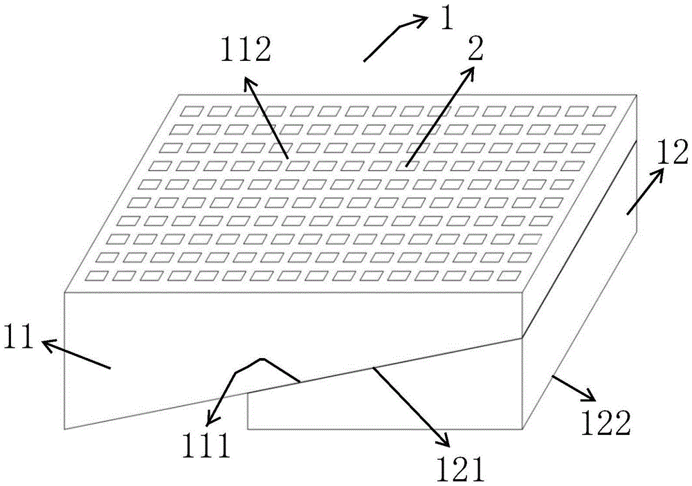
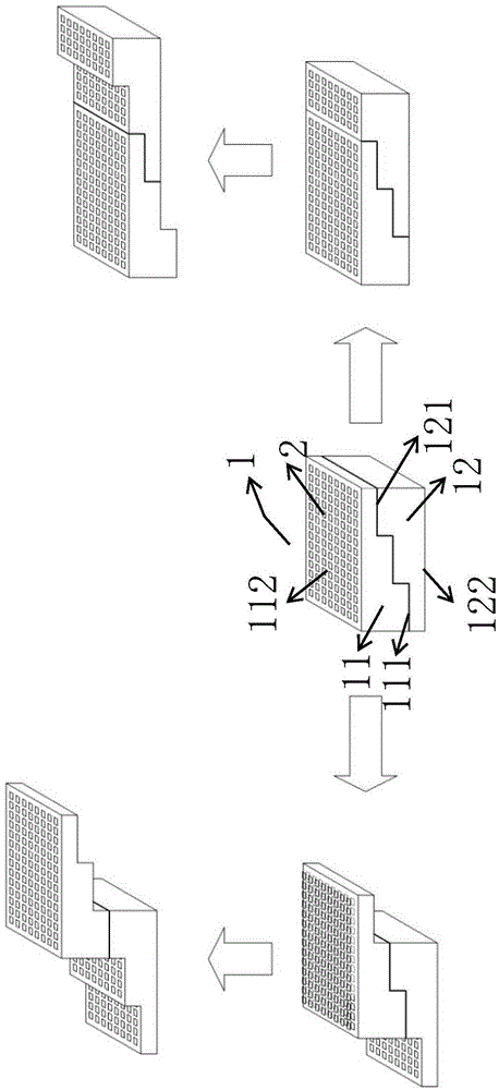
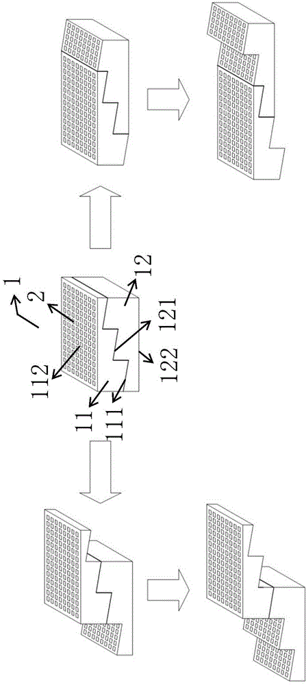
[0043] Before introducing the present invention in detail, the concepts of "collimation layer" and "dislocation coupling" are first defined. The collimation layer can be understood from two perspectives: one is to regard it as a sub-collimator obtained by dividing a collimator 1 (cutting the hole short); the other is to form a collimator by stacking it in series. Each of the plurality of collimators 1 of the collimation system. For a gamma photon to pass through a collimator containing multiple collimation layers, it must pass through each collimation layer in turn. Dislocation coupling means that the centerlines of the two collimation holes 2 do not overlap when the two collimation layers are coupled in series. On the contrary, t...


PUM


Abstract

The invention provides a collimator, a detection device with the collimator, and scanning equipment. The collimator comprises a first collimating layer and a second collimating layer, wherein the first collimating layer and the second collimating layer are arranged in a stacking way; each of the first collimating layer and the second collimating layer is provided with a plurality of collimating holes; the plurality of collimating holes formed in the first collimating layer have different hole depths; the plurality of collimating holes formed in the second collimating layer also have different hole depths; each of the first collimating layer and the second collimating layer has a butt joint surface; the plurality of collimating holes or the extending directions of the plurality of collimating holes penetrate through the corresponding butt joint surface; and the two butt joint surfaces are in opposite arrangement and can be anastomotic with each other. The effective hole depths after the stacking of the plurality of collimating holes formed in the first collimating layer and the second collimating layer can be changed through the relative movement of the first collimating layer and the second collimating layer, so that different resolutionS and sensitivity can be obtained.

Description

【Technical field】 [0001] The present invention mainly relates to the technical field of nuclear medical imaging, in particular to a collimator for collimating gamma rays, and a detection device and a scanning device having the collimator. 【Background technique】 [0002] Single Photon Emission Computed Tomograph (SinglePhotonEmissionComputedTomograph, hereinafter referred to as SPECT) is an advanced nuclear medicine molecular imaging tool, which can obtain metabolic information of organisms in a non-invasive way. It plays an important role in the mechanism research, diagnosis and treatment of major diseases. [0003] Spatial resolution and sensitivity are the two most important performance indicators of SPECT. Spatial resolution reflects SPECT's ability to resolve object details, and its improvement can increase the detail richness and clarity of the resulting image; sensitivity reflects SPECT's ability to detect low-activity objects, and its improvement can reduce the amoun...

Claims


Application Information

Patent Timeline
IPC IPC(8): A61B6/03G21K1/02
Inventor 李延召李炳轩
Owner WUHAN ZHIWEI TECH CO LTD
Why Eureka
Try Eureka