Deduster applied to treatment of flue gas from top of coke oven

A technology for flue gas treatment and dust collector, which is applied in the direction of removing smoke and dust, chemical instruments and methods, cleaning methods and utensils, etc. , the effect of reducing emissions

Inactive Publication Date: 2016-06-29
SICHUAN ANCHUANG ENVIRONMENTAL PROTECTION TECH CO LTD
View PDF0 Cites 1 Cited by
  • Summary
  • Abstract
  • Description
  • Claims
  • Application Information

AI Technical Summary

Problems solved by technology

The temperature of the coke discharge smoke is high, the instantaneous thermal buoyancy and the amount of dust are large, but the area ratio of the bucket-type dust collection hood between the top of the coke holding car and the top of the coke quenching car is very different, and the suction of the ground dust removal fan is mainly allocated to the coke quenching The bucket-type dust collection cover on the top of the carriage, and there is a gap between the coke-guiding grid-covered bucket-type dust collection cover and the small burner, so part of the smoke escapes from the small burner.
In order to improve the dust removal effect, some coking enterprises adopt the method of opening holes on the side plate of the bucket-type dust collection cover near the furnace body on the top of the coke guide grid and attaching a vehicle-mounted fan to assist dust collection. Some enterprises adopt the method of adjusting the dust removal fan of the ground station to run at high speed in advance The time parameter is used to pre-increase the suction force of the red coke in the initial grid entry stage; but the results are not satisfactory, and the power consumption is also increased

Method used


Image

  • Deduster applied to treatment of flue gas from top of coke oven
  • Deduster applied to treatment of flue gas from top of coke oven
  • Deduster applied to treatment of flue gas from top of coke oven

Examples


Embodiment 1

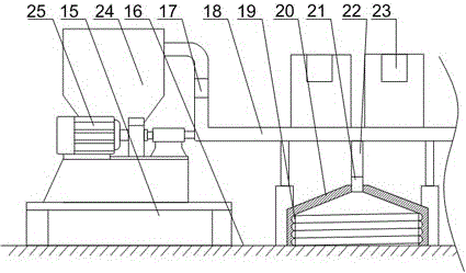
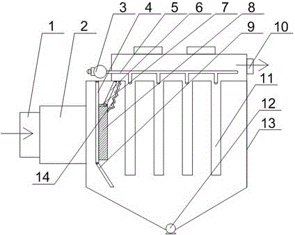
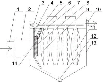
[0028] Such as Figure 1~Figure 3 As shown, the present embodiment is provided with a support seat 15 on the furnace roof baseline 16, and the fan 25 and the dust collector 24 are fixed on the support seat 15, and also includes a main gas pipe 18 and a plurality of gas collection hoods 20, the gas collection The cover 20 is covered on the outside of two adjacent coke-side small burners, and one end of the main air pipe 18 is connected with the air suction port of the blower fan 25 and the air inlet of the dust collector 24 respectively, and the other end of the main air pipe 18 is connected with the multi-layer air pipe through the bronchus 22. The two gas collection hoods 20 are connected; the gas collection hood 20 is composed of a collection section and a refraction section connected to each other. The collection section is cylindrical and has a spiral groove 19 on its inner wall along its axis direction. The refraction section is conical and its conical tip part communicat...


PUM


Abstract

The invention discloses a deduster applied to treatment of flue gas from the top of a coke oven. A support seat is arranged at a base line of the top of the coke oven, a fan and the deduster are fixed onto the support seat, the deduster comprises a main gas pipe and a plurality of gas trap hoods, the gas trap hoods just cover the top of the outer sides of two adjacent coke side small oven heads, one end of the main gas pipe is communicated with a suction opening of the fan and a gas inlet of the deduster while the other end of the main gas pipe is communicated with the plurality of gas trap hoods by branch gas pipes, the gas trap hoods are composed of collecting sections and refracting sections connected with each other, spiral slots are formed in the inner walls of the collecting sections axially, and the conical top parts of the conical refracting sections are communicated with the tail ends of the branch gas pipes. When the deduster works, the plurality of gas trap hoods are simultaneously used for collecting flue gas escaping from the small oven heads at the base line of the top of the coke oven in a concentrated manner, and the collected flue gas enters the main gas pipe by the branch gas pipes and then is drawn into a dust filter to be treated by traction of air force of the fan, so that the flue gas is prevented from escaping from the top of the coke oven and polluting the environment.

Description

technical field [0001] The invention relates to the technical field of coking and environmental protection, in particular to a dust collector used for coke oven roof flue gas treatment. Background technique [0002] Coking is a multi-source pollution industry, and smoke and dust are the main pollutant fugitives in the coking production process. Modern chamber coke ovens are generally equipped with vehicle-mounted or ground station coal charging and coke discharge dust removal systems, of which the ground station dust removal system is widely used. The ground station type coke discharge dust removal system mainly uses hydraulic coupling or frequency conversion control fans to collect most of the smoke dust on the coke side through the collection cover set on the coke stop car and purifies it through the coke discharge dust collector. However, part of the smoke and dust still escapes from the small burner head on the coke side, which deteriorates the working environment. The...

Claims


Application Information

Patent Timeline
Patent Type & Authority Applications(China)
IPC IPC(8): B01D50/00B01D46/04B08B15/02
CPCB01D46/023B01D46/04B08B15/02B01D50/20
Inventor 陈昱
Owner SICHUAN ANCHUANG ENVIRONMENTAL PROTECTION TECH CO LTD
Why Eureka
Try Eureka