

Special cutter bar for boring inner annular grooves of deep-long holes
A special tool holder, deep and long hole technology, applied in boring bars and other directions, can solve the problems of poor axial dimensional accuracy, aggravated tool wear, large cutting force, etc., to reduce cylindricity error, improve local rigidity, and improve tool holder The effect of stiffness
- Summary
- Abstract
- Description
- Claims
- Application Information
AI Technical Summary
Problems solved by technology
Method used
Image

Examples
Embodiment
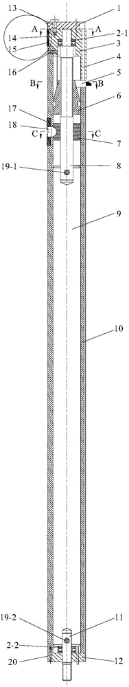
[0042] Such as figure 1 It is a schematic diagram of the longitudinal section of the segmented special boring bar for deep hole annular inner groove boring with guiding double supports of the present invention. It is mainly suitable for the boring process of small diameter deep long holes and deep long hole annular grooves. The length-to-diameter ratio of the boring bar is 17:1, and the diameter of the main body of the tool bar is 21mm. The boring bar is composed of a guide part, a cutter head part, a tool advance and retreat control part, an axial positioning part, an auxiliary support part and a rod body part. The guide part and the auxiliary support part provide support for the cutter head part, reducing stress deformation at the cutter head. The rear mandrel in the body section is made of a material with a high modulus of elasticity, which further increases the overall rigidity of the shank. The cutter head part is provided with three uniformly arranged blades, most of t...
PUM
 Abstract
Description
Claims
Application Information