Magnetorheological pressure control valve

A pressure control, magnetorheological technology, applied in the direction of lift valve, valve details, valve device, etc., can solve the problems of small valve core movement, high valve core spring requirements, affecting the control valve, etc., and achieve a large pressure control range , Flexible magnetic circuit direction, reducing the effect of coil heating

Active Publication Date: 2016-06-29
浙江孔辉汽车科技有限公司
View PDF8 Cites 1 Cited by
  • Summary
  • Abstract
  • Description
  • Claims
  • Application Information

AI Technical Summary

Problems solved by technology

In the traditional design, the machining accuracy is high, and the product consistency is poor; the requirements for the valve core spring are very high, and it is not easy to realize the rapid and stepless pressure change; the valve core movement is generally small; the power consumption is very low. Large, energy efficiency is not high; under a certain volume requirement, the pressure adjustable range is small
[0003] The disadvantage of the magnetorheological pressure control valve described in the prior application ZL201220409103.X is that the structure required to achieve the effect of pressure control is too complicated, the required sensors are expensive and the control method is complicated; the inside of the valve body Four O-ring seals are used, which is cumbersome for processing and assembly; the coil assembly is arranged outside the working chamber, which limits the effective size of the working chamber; in addition, the magnetic field lines of the designed magnetic field need to be established with the help of a valve outside the valve body. structure, which affects the maximization of the intended effect of the control valve

Method used


Image

  • Magnetorheological pressure control valve
  • Magnetorheological pressure control valve
  • Magnetorheological pressure control valve

Examples


Embodiment Construction

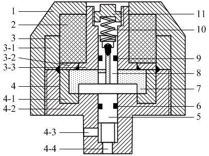
[0014] attached by figure 1 As shown: the magnetorheological pressure control valve includes: a valve cover 1, a coil assembly 2 composed of a coil and a magnetic isolation jacket, an upper valve body 3, a lower valve body 4, a lower valve core 5, and a magneto-rheological fluid inside. Working chamber 7, upper spool 8, return spring 10, adjusting nut 11 and multiple rubber sealing rings (6, 9). The bonnet is a magnetic material, and the bonnet 1 and the lower valve body 4 are threadedly connected to the upper and outer sides of the lower valve body 4; the lower valve body 4 is magnetically guided by the lower valve body magnetic isolation ring 4-1 and the lower valve body The main body 4-2 is welded, the lower valve body 4 and the upper valve body 3 are welded on the lower side of the upper valve body 3, the upper valve body 3 is composed of the upper valve outer magnetic guide ring 3-1, the upper valve body magnetic isolation ring 3- 2 and the magnetic guide ring 3-3 in the...


PUM


Abstract

The invention relates to a magnetorheological pressure control valve. The magnetorheological pressure control valve comprises a valve cover, a coil assembly 2, an upper valve body, a lower valve body, a lower valve core, a first rubber seal ring, a second rubber seal ring, a work cavity, an upper valve core, a reset spring and an adjusting nut. The valve cover is fixedly connected to the upper outer side of the lower valve body. The adjusting nut is connected to the inner side of the upper valve body. The reset spring in the compressed state is arranged under the adjusting nut. The lower portion of the reset spring presses on the upper valve core. The upper valve core is arranged in the upper valve body. The lower portion of the upper valve core presses at the upper end of a disk on the lower valve core. The lower valve core is arranged in the lower valve body. The lower portion of the lower valve core presses on the upper side of an oil inlet of the lower valve body. The work cavity is formed between the upper valve body and the lower valve body. The coil assembly is arranged in a groove of the upper valve body. The upper side of the coil assembly makes contact with the inner side of the valve cover. According to the magnetorheological pressure control valve, the coil assembly is arranged on the upper side of the work cavity and far away from magnetorheological fluid, so that the influence of heating of an electromagnetic coil on the magnetorheological fluid is smaller, and the heat dissipation effect of the magnetorheological fluid is better.

Description

technical field [0001] The invention relates to a magneto-rheological pressure control valve, in particular to controlling the opening pressure of the valve by controlling the extrusion force of the magneto-rheological fluid received by the valve core during its movement, so as to realize the pressure control of the hydraulic system. magnetorheological pressure control valve. Background technique [0002] Common pressure control valves usually control the system pressure by controlling the preload of the spool spring. Traditional pressure control valves control the pre-tightening force of the control spool spring by changing the magnetic field of the electromagnetic coil, thereby changing the force required for the spool to open, and then controlling the system pressure. In the traditional design, the machining accuracy is high, and the product consistency is poor; the requirements for the valve core spring are very high, and it is not easy to realize the rapid and stepless...

Claims


Application Information

Patent Timeline
Patent Type & Authority Applications(China)
IPC IPC(8): F16K1/00F16K31/12F16K31/06F16F9/34F16F9/53
Inventor 郭孔辉刘洋章新杰
Owner 浙江孔辉汽车科技有限公司
Why Eureka
Try Eureka