Electromagnetic microvalve device

A microvalve and electromagnetic technology, applied in the field of microfluidics, can solve the problems of unfavorable microfluidics system integration and miniaturization, expensive manufacturing process, large volume of iron core coils, etc., and achieve good electrical connection stability, perfusion production Convenience, low cost effect

Active Publication Date: 2018-04-27
TECHNICAL INST OF PHYSICS & CHEMISTRY - CHINESE ACAD OF SCI
View PDF4 Cites 2 Cited by
  • Summary
  • Abstract
  • Description
  • Claims
  • Application Information

AI Technical Summary

Problems solved by technology

The iron core coil is bulky and cannot be integrated into the valve, which is not conducive to the integration and miniaturization of the microfluidic system; although the thin film coil can be integrated into the valve, the required sputtering, deposition and other manufacturing processes are expensive and complicated

Method used


Image

  • Electromagnetic microvalve device
  • Electromagnetic microvalve device
  • Electromagnetic microvalve device

Examples


Embodiment Construction

[0024] The specific implementation manners of the present invention will be further described in detail below in conjunction with the accompanying drawings and embodiments. The following examples are used to illustrate the present invention, but are not intended to limit the scope of the present invention.

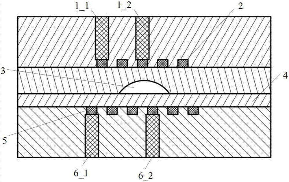
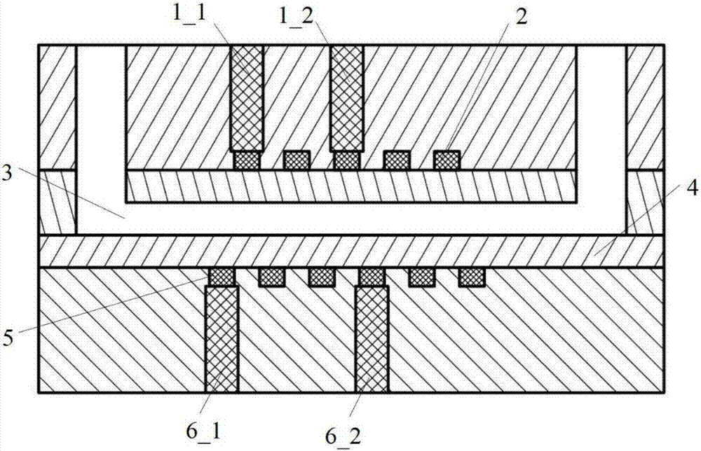
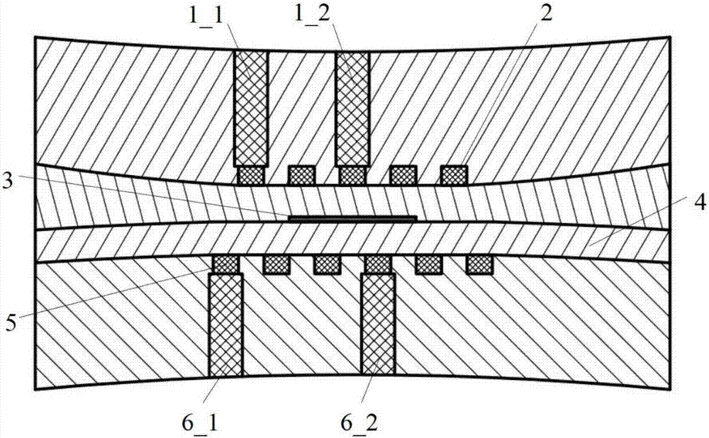
[0025] figure 1 It is a schematic cross-sectional view of an electromagnetic microvalve device in an open state according to an embodiment of the present invention; figure 2 yes figure 1 The longitudinal sectional schematic diagram of the electromagnetic microvalve device shown in the open state; refer to Figure 1~2 , the device includes: a sample reagent channel 3, a first liquid metal helical coil microchannel 5 filled with room temperature liquid metal, a second liquid metal helical coil microchannel 2 filled with room temperature liquid metal, and a flexible film 4;

[0026] The first liquid metal helical coil microchannel 5 and the second liquid metal helical coi...


PUM


Abstract

The invention discloses an electromagnetic micro-valve device, and relates to the technical field of microfluidics. The device comprises a sample reagent runner, first liquid metal spiral coil micro runners filled with room-temperature liquid metal, second liquid metal spiral coil micro runners filled with room-temperature liquid metal and a flexible film. Closing and opening of the sample reagent runner are achieved through attraction force and repulsive force among the liquid metal spiral coil micro runners filled with the room-temperature liquid metal, and the purpose of controlling fluid flowing can be rapidly achieved. The structure is compact, pouring and manufacturing are convenient, cost is low, and integration is easy. In addition, due to the fact that the liquid metal with which the liquid metal spiral coil micro runners are filled has mobility and deformability, in the process of valve closing and valve opening through electromagnetic drive extrusion, fractures cannot happen, and electric connecting stability is good.

Description

technical field [0001] The invention relates to the field of microfluidic technology, in particular to an electromagnetic microvalve device. Background technique [0002] The electromagnetic microvalve uses the electromagnetic force generated by the electromagnetic coil to squeeze the microchannel and block the microflow. The existing electromagnetic microvalve mainly uses iron core coils or thin film coils to generate electromagnetic force. In this type of microvalve, a coil is respectively arranged on the upper side and the lower side of the sample reagent microchannel. When the coils on both sides are loaded with current in the same direction to generate a magnetic field in the same direction, the two coils will attract each other and squeeze the micro-channel in the middle, and the micro-valve will close; otherwise, the micro-valve will open. Alternatively, the coils on one of the upper and lower sides of the sample reagent can also be permanent magnets. The iron core ...

Claims


Application Information

Patent Timeline
Patent Type & Authority Patents(China)
IPC IPC(8): F16K99/00B81B3/00
CPCF16K99/0026F16K99/0046F16K2099/0074
Inventor 詹士会高猛桂林
Owner TECHNICAL INST OF PHYSICS & CHEMISTRY - CHINESE ACAD OF SCI
Why Eureka
Try Eureka