Underwater low-disturbance separation device

A separation device, low-disturbance technology, applied in the directions of mines, offensive equipment, weapon types, etc., can solve the problems that the warhead is difficult to maintain the vertical state, the separation device has a large separation stroke, and there is lateral moment, etc., to reduce the impact, The effect of short separation time and no hysteresis in response

Inactive Publication Date: 2016-06-29
710TH RES INST OF CHINA SHIPBUILDING IND CORP
View PDF5 Cites 5 Cited by
  • Summary
  • Abstract
  • Description
  • Claims
  • Application Information

AI Technical Summary

Problems solved by technology

Since the separation device is installed inside the nozzle of the engine, the length of the separation device is too long, which makes the separation stroke too long, and the separation process is affected by the jet flow of the nozzle, which will cause great interference to the warhead during the separation process
In addition, the second half of the connecting rod of the separation device is connected to the separation plate at a certain angle. There is a lateral moment during the separation process, which also causes interference to the warhead during the separation process. The above factors make it difficult for the warhead to remain vertical during initial launch. state

Method used


Image

  • Underwater low-disturbance separation device
  • Underwater low-disturbance separation device
  • Underwater low-disturbance separation device

Examples


Embodiment Construction

[0029] The present invention will be described in detail below with reference to the accompanying drawings and examples.

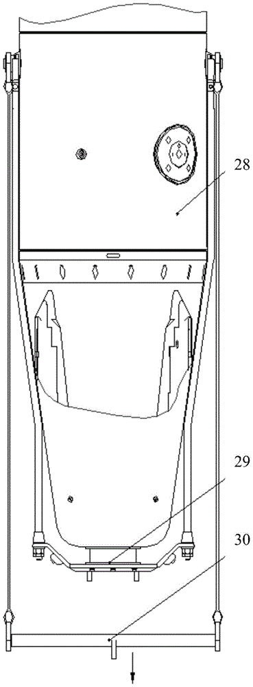
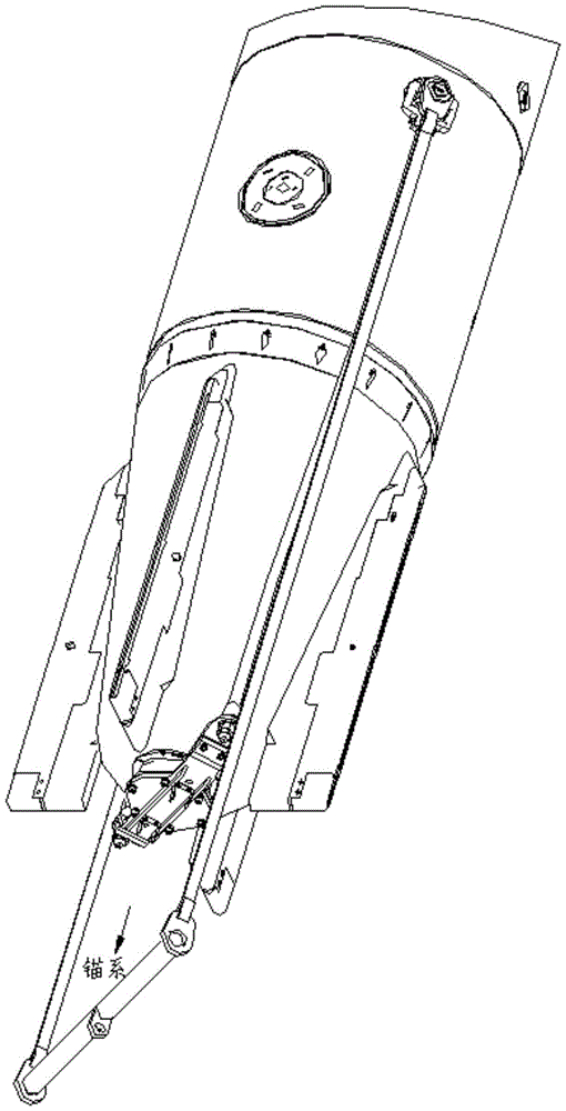
[0030] as attached figure 1 and 2 As shown, the present invention provides an underwater low-disturbance separation device. The separation device 29 connects the mooring system 30 and the floating warhead 28 into one body. The mooring system 30 makes the floating warhead 28 hover at a designated position underwater.

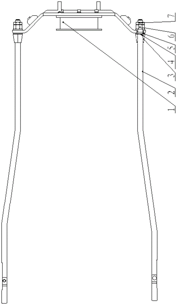
[0031] as attached image 3 As shown, the separation device 29 includes: a separation component 1 , a connecting rod set 2 , a sheath 3 , an adjusting washer 4 , an isolation washer 5 , a lock nut 6 and a lock nut 7 . The separating part 1 of the device is connected with the mounting surface of the tail of the floating warhead through screws, and an O-shaped sealing ring 10 is installed between the separating part 1 and the floating warhead for sealing. The clamping frame 25 of the connecting rod group 2 is connected with the mooring seat ...


PUM


Abstract

The invention discloses an underwater low-disturbance separation device and belongs to the technical field of mechanical structures. The underwater low-disturbance separation device is applied to a vertical floating warhead of a long-range self-propelled naval mine. Due to the low-disturbance separation function of the underwater low-disturbance separation device, the initial launching disturbance of an engine can be reduced, finally the quality of a floating trajectory is improved, and trajectory distribution is reduced. In the service period, the vertical floating warhead is moored underwater in a two-point mode through the separation device and a mooring system installed at the tail portion of the vertical floating warhead so as to be concealed for waiting to make an attack; when an attack instruction is received, the engine is started, and the internal pressure of the engine is rapidly increased through generated fuel gas; when the internal pressure reaches a certain value, a limiting plug of the separation device is pushed to cut off a shear pin and move downwards, and limiting on a steel ball is relieved; and when the working pressure of the engine is larger than the environment pressure, an inner shell of the separation device moves and is separated from an engine connecting flange, a connecting rod is driven to disengage from the vertical floating warhead, and the warhead is separated from the mooring system and starts to vertically float to attack a target. Sealing, underwater two-point mooring, underwater ignition liberation, underwater corrosion resistance, parasitism resistance and the like of the underwater floating warhead can be realized through the underwater low-disturbance separation device.

Description

technical field [0001] The invention relates to a separation mechanism, in particular to a low-disturbance separation device for underwater separation of vertically floating warheads, and belongs to the technical field of mechanical structures. Background technique [0002] During the service period of the long-range self-propelled mine, the warhead is hidden under the water through the separation device installed at its tail and the mooring system. When the warhead receives the attack command, the separation device moves and separates from the mooring system. The warhead rises vertically to attack the target. [0003] Breakaway devices are currently used on outboard engines and use a compressed spring to unlock the lock. Since the separation device is installed inside the nozzle of the engine, the length of the separation device is too large to make the separation stroke too long, and the influence of the jet flow of the nozzle during the separation process will cause grea...

Claims


Application Information

Patent Timeline
Patent Type & Authority Applications(China)
IPC IPC(8): F42B22/10
CPCF42B22/10
Inventor 廉斌赵家鹏刘延平吕维乐聂晓敏吴旌尚奇
Owner 710TH RES INST OF CHINA SHIPBUILDING IND CORP
Why Eureka
Try Eureka