
A magnetically stirred flow cytometer flow chamber

A flow cytometer and magnetic stirring technology, applied in the field of flow chamber, can solve the problems of sheath liquid in sheath liquid chamber, sample contamination of flow chamber, easy blocking of nozzles, etc., and achieves reduced instrument accuracy, large volume, and convenient casting. Effect

Active Publication Date: 2018-04-17
ANHUI NORMAL UNIV
View PDF9 Cites 0 Cited by
  • Summary
  • Abstract
  • Description
  • Claims
  • Application Information

AI Technical Summary

Problems solved by technology

[0005] But they didn't solve the sheath fluid chamber. The sheath fluid starts to have velocity in the flow chamber, especially when the machine is turned on, it takes a long time to form a stable laminar flow.
Easy to clog the jet or contaminate the flow cell with sample during continuous injection

Method used


Image

  • A magnetically stirred flow cytometer flow chamber
  • A magnetically stirred flow cytometer flow chamber

Examples


Embodiment 1

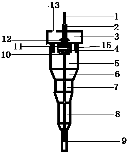
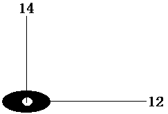
[0032] Such as figure 1 , figure 2 A flow cytometer flow chamber of a magnetic stirring type is shown, comprising a flow chamber, a sampling needle 1, and a sheath fluid chamber 3, wherein the sampling needle 1 passes through the flow chamber and the sheath fluid chamber 3, and the The sheath fluid chamber 3 is located above the flow chamber and connected through the sheath fluid hole 4 ; magnetic beads are arranged in the flow chamber, and an electromagnet 11 is arranged between the flow chamber and the sheath fluid chamber 4 .

[0033] Furthermore, the flow chamber is divided into flow chamber 5, flow chamber 2, and flow chamber 8 from top to bottom, and an upper width Lower narrow transition section 6 .

[0034] Further, the first flow chamber 5 , the second flow chamber 7 , and the third flow chamber 8 are all cylinders, and the cross-sectional area of ​​the first chamber 5 is smaller than that of the second chamber 7 ; the cross-sectional area of ​​the second chamber 7...


PUM


Abstract

The invention relates to a flowing chamber of a flow cytometry and particularly relates to a magnetic stirring type flow cytometry flowing chamber. The magnetic stirring type flow cytometry flowing chamber comprises a flowing chamber body, a sample feeding needle and a sheath liquid chamber, wherein the sample feeding needle penetrates through the flowing chamber body and the sheath liquid chamber; the sheath liquid chamber is located above the flowing chamber body and is connected with the flowing chamber body through a sheath liquid hole; the flowing chamber body is internally provided with a magnetic bead; an electromagnet is arranged between the flowing chamber body and the sheath liquid chamber; and a sheath liquid inlet is formed at the upper end of the sheath liquid chamber. The magnetic stirring type flow cytometry flowing chamber can be used for rapidly stabilizing a laminar flow and saving energy sources. The sheath liquid still has a centripetal force when the sheath liquid is sprayed out from a nozzle; and the sample feeding needle is located at the circle center and is located at the position of a typhoon eye, so that the sample feeding needle can fall off in a straight line, is not mixed with the sheath liquid and does not block the nozzle.

Description

technical field [0001] The utility model relates to a flow chamber of a flow cytometer, in particular to a flow chamber of a magnetic stirring type flow cytometer. Background technique [0002] Flow cytometer is a very common detection instrument. The flow chamber in its liquid circuit system is composed of sample tube, sheath liquid tube and nozzle. It is usually made of transparent and stable materials such as optical glass and quartz. The design and production are very fine, it is the heart of the fluid flow system. The sample tube stores the sample, and a single cell suspension is ejected from the sample tube under the action of the liquid flow pressure; the sheath liquid flows from the sheath liquid tube from the surrounding to the nozzle hole, surrounds the sample and then ejects from the nozzle to ensure a stable liquid flow. Due to the effect of the sheath fluid, the detected cells are confined to the axis of the fluid flow. Typically, the sample is injected into t...

Claims


Application Information

Patent Timeline
Patent Type & Authority Patents(China)
IPC IPC(8): G01N15/14
CPCG01N15/1404G01N2015/1409
Inventor 闫浩马晓艳林凌张庭廷
Owner ANHUI NORMAL UNIV
Learn More