Embedded part detection system and method for PC component production line
A technology of detection system and embedded parts, which is applied in the field of detection system to achieve the effect of improving accuracy and reliability, improving detection accuracy and efficiency, and saving energy
- Summary
- Abstract
- Description
- Claims
- Application Information
AI Technical Summary
Problems solved by technology
Method used
Image
Examples
Embodiment 1
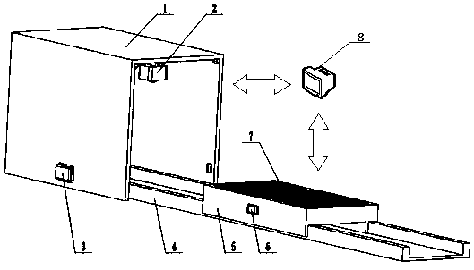
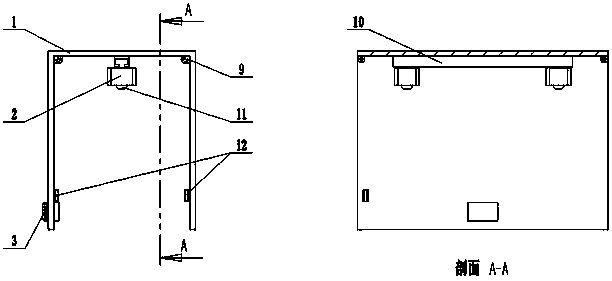
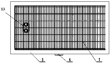
[0042] see Figure 1~Figure 3 , the embedded parts inspection system of this PC component production line, including: image acquisition room 1, two camera vibration reduction devices 2, RFID fixed reader 3, track 4, PC mold 5, RFID tag 6, steel cage 7, Computer 8, six LED supplementary light sources 9, camera rail 10, two cameras 11 and photoelectric switch 12. The embedded part 13 to be tested is located inside the steel cage 7, the steel cage 7 is located inside the PC mold 5, and the RFID tag 6 is fixed on the outside of the PC mold 5; the PC mold 5 is slid on the track 4, and the track 4 passes through the image acquisition room 1; The RFID fixed reader 3 is placed in the middle of the image collection room 1 and is at the same height as the RFID tag 6. The photoelectric switch 12 is placed at the front end of the image collection room 1 and is at the same height as the PC mold 5. Six LED supplementary light sources 9 are distributed At the middle and top corners of both ...
Embodiment 2
[0044] This embodiment is basically the same as Embodiment 1, and the features are as follows:
[0045] In the embedded parts detection system of the PC component production line, the six LED supplementary light sources 9 are placed in the middle and top corners of both sides of the image acquisition room 1, and the position arrangement ensures that the light in the image acquisition room 1 is sufficient and evenly distributed. The LED supplementary light source 9 is used as a supplementary light source when the camera 11 collects images. The photoelectric switch 12 is arranged at the bottom position of the image acquisition chamber 1, and is at the same height as the PC mold 5, and the placement position ensures that when the PC mold 5 enters the image acquisition chamber 1 as a whole, two cameras 11 are started to collect images.
[0046] The camera guide rail 10 is placed in the middle of the top of the image acquisition chamber 1, and the two camera vibration reduction dev...
Embodiment 3
[0049] see Figure 1~Figure 6 , the embedded parts detection system and method of this PC component production line, adopt the above-mentioned system to operate, and the specific operation steps are as follows:
[0050] 1) Image acquisition
[0051] Two cameras 11 positioned at the top of the image acquisition chamber 1 carry out image acquisition to the PC mold 5 at the same time, and obtain two images of the PC mold 5;
[0052] 2) Image stitching
[0053] Project the images of the PC mold 5 obtained in step 1 into a unified coordinate system, and use the nonlinear least squares method to optimize to obtain the image stitching transformation matrix, and stitch the overlapping areas of the two images to form a complete PC Die 5 panorama image;
[0054] 3) Establish a PC mold library with embedded parts
[0055] Establish a PC mold library containing embedded parts, and at the same time establish a corresponding relationship between the PC mold library containing embedded p...
PUM
 Abstract
Description
Claims
Application Information
 - R&D
- Intellectual Property
- Life Sciences
- Materials
- Tech Scout
- Unparalleled Data Quality
- Higher Quality Content
- 60% Fewer Hallucinations
Browse by: Latest US Patents, China's latest patents, Technical Efficacy Thesaurus, Application Domain, Technology Topic, Popular Technical Reports.
© 2025 PatSnap. All rights reserved.Legal|Privacy policy|Modern Slavery Act Transparency Statement|Sitemap|About US| Contact US: help@patsnap.com


