
Portable intelligent waveform recording four-channel partial discharge detector

A waveform recording, intelligent technology, applied in the direction of instruments, measuring electricity, measuring devices, etc., can solve the problems of accelerated insulation defects, residual insulation phenomenon, equipment failure power accidents, etc., to achieve the effect of simple trigger loop and economical detection method

Active Publication Date: 2018-05-08
广州智丰电气科技有限公司
View PDF6 Cites 0 Cited by
  • Summary
  • Abstract
  • Description
  • Claims
  • Application Information

AI Technical Summary

Problems solved by technology

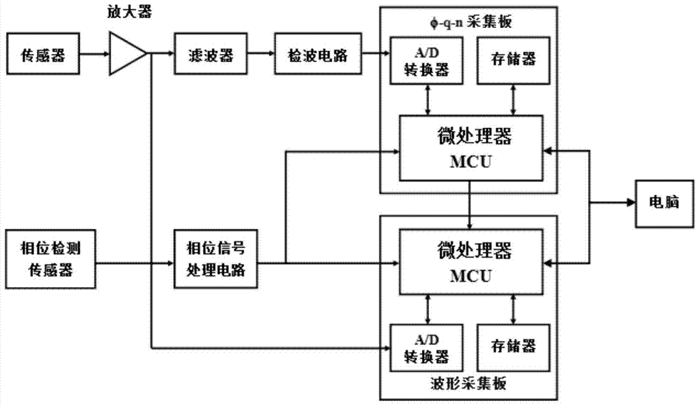
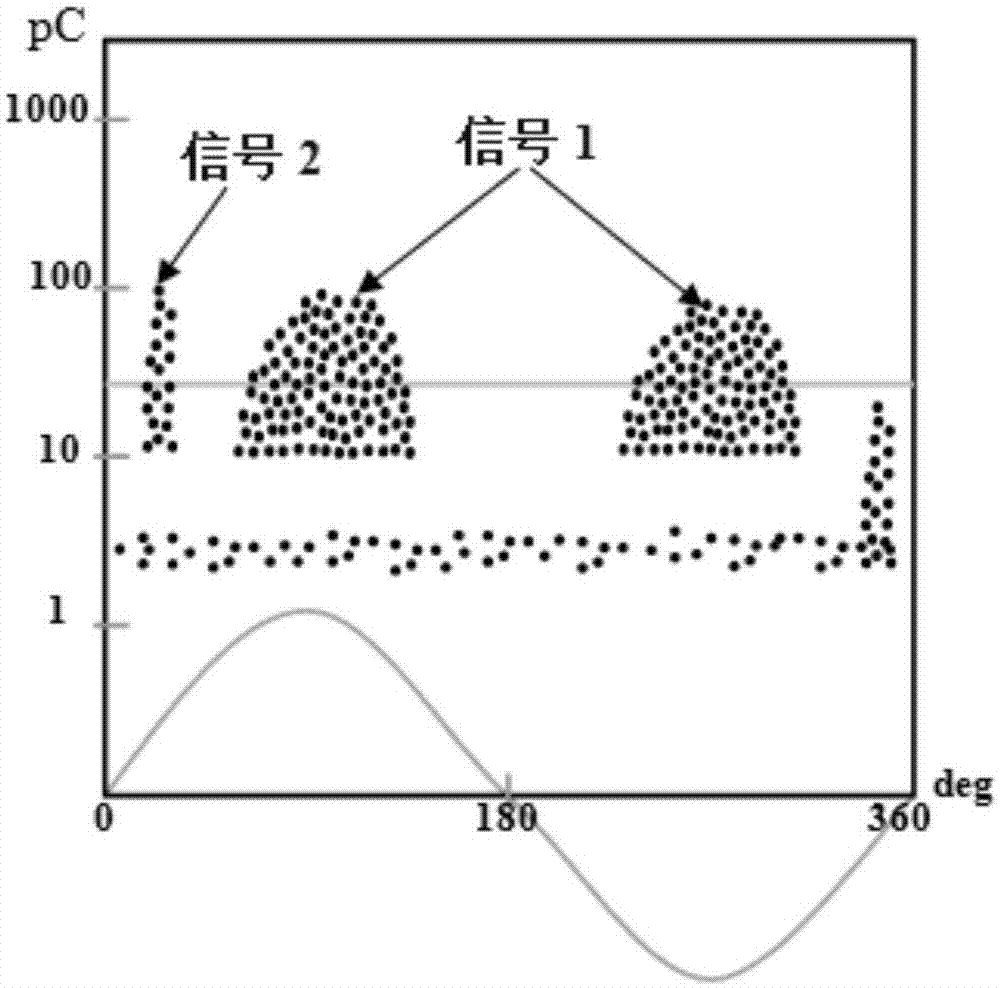
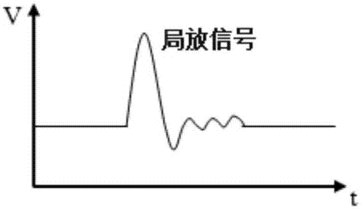
[0002] It is inevitable that high-voltage equipment will leave insulation during installation, and aging will occur during long-term use. These insulation defects and aging are prone to partial discharge, and the existence of partial discharge will in turn increase and accelerate insulation defects. Aging phenomenon can even cause insulation breakdown, that is, the occurrence of equipment failure or power accident, and then produce indirect or direct economic losses; therefore, partial discharge detection of high-voltage power equipment is an effective measure to prevent sudden equipment failure , because during the partial discharge test of the cable line, there are various environmental noises at the test site. Some of these interference signals come from the inside of the cable, and some come from the outside of the cable. The PD signal and these environmental noises are mixed together. How to extract the partial discharge signal from the mixed signal is a technical problem; figure 1 As shown, the partial discharge sensor is used to collect various signals on the cable line, and the collected signal is amplified by the amplification module and then transmitted to the waveform acquisition board to collect and save the original waveform. The other path is transmitted to the filter. The collected signal is filtered and transmitted to the detection circuit. The detection circuit processes the signal into the required analog signal and outputs it to the φ-q-n acquisition board. The φ-q-n acquisition board converts the analog waveform into the required φ, q, The n, t, f digital data are transmitted to the computer, and the trigger gate value of the signal φ-q-n spectrum is manually or automatically set through the computer, and the trigger gate value is transmitted to the waveform acquisition board for waveform triggering. This trigger mode is above the trigger line The waveform of the φ-q-n spectrum can be triggered, and the phase information collected by the phase sensor on the loop is transmitted to the phase signal processing loop and connected to the φ-q-n board and the waveform board to synchronize the φ-q-n and waveform; figure 2 As shown, the principle of triggering the waveform through φ-q-n is: when the trigger gate value of the φ-q-n spectrum is set at figure 2 At the position of the yellow line, the waveform signal above the yellow line will be triggered, that is, the waveform of signal 1 and signal 2 will be triggered, and there are two waveform signals after triggering, namely image 3 , Figure 4 , in the existing trigger mode, the waveform signals above the trigger threshold can be triggered, but the waveform signals cannot be classified, and the waveform signals below the trigger threshold can neither be triggered nor classified. Of course, the more signals above the trigger line The more waveform signals are triggered, the more complex they are; the existing trigger method is to trigger the waveform signal according to the trigger threshold value set by the φ-q-n spectrum. This method can only be used for waveforms above the trigger threshold value in the φ-q-n spectrum. The signal triggers, and the waveform signal below the trigger threshold value cannot be triggered, that is, the higher the trigger threshold value, the fewer signals are triggered, and the lower the trigger threshold value, the more signals are triggered. This waveform trigger method is single, and waveform classification is difficult. The circuit and program are also more complex, its operability is low, and the cost is high; the existing waveform classification technology uses the original waveform to do wavelet analysis and Fourier transform analysis, which requires a lot of time technically and is difficult to achieve synchronization At the same time, performing these analysis and processing tasks will make the load on the MCU heavy, and require a large number of programs, and its speed response is also limited, making secondary and tertiary development very difficult

Method used


Image

  • Portable intelligent waveform recording four-channel partial discharge detector
  • Portable intelligent waveform recording four-channel partial discharge detector
  • Portable intelligent waveform recording four-channel partial discharge detector

Examples


Embodiment 1

[0058] The trigger gate value is automatically set by the software, and the trigger value automatically set by the software is △t 1 , Δt 2 , Δt 3 three groups, of which

[0059] The trigger value automatically set by the software is △t 1 , the a signal is triggered,

[0060] The trigger value automatically set by the software is △t 2 , the b signal is triggered,

[0061] The trigger value automatically set by the software is △t 3 , the signals a and b are triggered,

[0062] Signal classification can be realized by automatically setting the interval trigger threshold value, as shown in the attached Figure 11-14 shown.

Embodiment 2

[0064] By manually setting the threshold value of the trigger interval, two trigger lines T1 and T2 are manually set, and the set trigger line determines the trigger threshold interval △t 1 , then △t 1 The signal in the interval is triggered, that is, the waveform b is triggered, as shown in the attached Figure 15-16 shown.

[0065] The working principle of the present invention is: the sensor collects the signal on the cable line, the analog signal collected is amplified by the amplifier and then transmitted to the first waveform acquisition board, and the A / D of the data is performed by the microprocessor MCU in the first waveform acquisition board Convert and store, and transmit to the computer to display various signal waveforms. At the same time, set multiple trigger thresholds according to the original waveform. The set multiple trigger values ​​are transmitted to the second waveform acquisition board, and the second waveform acquisition board performs conditional sele...


PUM


Abstract

The invention discloses a portable intelligent waveform-recording four-channel partial discharge detector. The portable intelligent waveform-recording four-channel partial discharge detector comprises a housing. The housing is internally provided with a sensor, an amplifier, an attenuator, a first waveform collection board and a second waveform collection board. The sensor collects cable line signals, the cable line signals are amplified by the amplifier, one path of processed signals is transmitted to the second waveform collection board for original waveform collection and storage, and unsaturated original waveforms of the other path of the processed signals are transmitted through the attenuator to the first waveform collection board for processing. If the input original signals are too large and lead to signal deformation, then after an MCU of the first waveform collection board distinguishes the sizes of the original signals, the information of relatively large signals is fed back to the attenuator for attenuation, the signals are transmitted to the first waveform collection board again for processing and then are transmitted to a computer. The two paths of signals of the first waveform collection board and the second waveform collection board are finally transmitted to the computer for analysis and display. According to the invention waveform classification is realized by composition of trigger gate values, and the portable intelligent waveform-recording four-channel partial discharge detector is economic, convenient and highly-efficient.

Description

technical field [0001] The invention relates to a partial discharge detection device, in particular to a portable intelligent waveform recording four-channel partial discharge detector. Background technique [0002] It is inevitable that high-voltage equipment will leave insulation during installation, and aging will occur during long-term use. These insulation defects and aging are prone to partial discharge, and the existence of partial discharge will in turn increase and accelerate insulation defects. Aging phenomenon can even cause insulation breakdown, that is, the occurrence of equipment failure or power accident, and then produce indirect or direct economic losses; therefore, partial discharge detection of high-voltage power equipment is an effective measure to prevent sudden equipment failure , because during the partial discharge test of the cable line, there are various environmental noises at the test site. Some of these interference signals come from the inside o...

Claims


Application Information

Patent Timeline
Patent Type & Authority Patents(China)
IPC IPC(8): G01R31/12
CPCG01R31/1272
Inventor 东盛刚浦野幸治唐敏玲董霖鲁晶晶
Owner 广州智丰电气科技有限公司
Learn More