
Copper stranded wire pressing structure

A technology of crimping structure and copper stranded wire, applied in conductor/cable supply devices, electrical components, circuits, etc., can solve the problems of stress concentration, reduction of copper stranded wire tension, and copper stranded wire relaxation, etc., to increase the tension, The effect of avoiding jumping and avoiding metal fatigue

Inactive Publication Date: 2016-06-29
CHENGDU XINGDA OF COPPER CO LTD
View PDF3 Cites 1 Cited by
  • Summary
  • Abstract
  • Description
  • Claims
  • Application Information

AI Technical Summary

Problems solved by technology

However, when the copper stranded wire is rewound, a motor drives the reel to rotate, and the copper stranded wire is drawn to the reel from the outlet of the stranding machine, because the reel body rotates continuously with the motor, and the copper stranded wire is pulled There will be a certain degree of radial runout, that is, local stress concentration on the copper strands; and once the reel motor stops, the tension of the drawn copper strands will directly decrease, that is, the copper strands will be slack, Causes uneven distribution of copper strands on the reel

Method used


Image

  • Copper stranded wire pressing structure
  • Copper stranded wire pressing structure
  • Copper stranded wire pressing structure

Examples


Embodiment 1

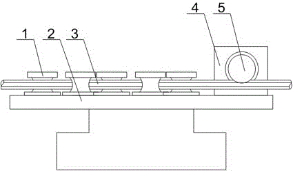
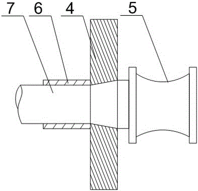
[0021] Such as Figure 1~Figure 3 As shown, this embodiment includes a workbench 2 and two rows of staggered lateral pressure rollers 1 installed on the workbench 2, and a support plate 4 is also arranged on the workbench 2, and the support plate 4 A sleeve 6 is installed on one side, and a tapered hole coaxial with the sleeve 6 is opened on the support plate 4. The connecting rod 7 is composed of a straight section, an enlarged section, and an extension section whose ends are sequentially connected. The straight section is provided with threads, and the sleeve 6 is threadedly connected with the straight section, and the tapered hole fits with the enlarged section in clearance, and a pressing roller 5 is connected at the end of the extended section, and the inner diameter of the expanded section is along the The axis of the sleeve 6 points toward the direction of the roller 5 and increases progressively. When working, the copper strand 3 moves along the aisle formed by two ro...


PUM


Abstract

The invention discloses a copper stranded wire crimping structure, including a workbench and two rows of side pressure rollers, a support plate is also arranged on the workbench, a sleeve is installed on one side of the support plate, and a sleeve and sleeve are opened on the support plate. Concentric tapered holes, threads are provided on the straight section, the sleeve is threaded with the straight section, the tapered hole is matched with the enlarged section, and the end of the extended section is connected with a pressing roller. The inner diameter of the enlarged section Incremental along the axis of the sleeve pointing toward the roller. When the copper stranded wire jumps radially due to factors at the power output end, the groove on the pressing roller directly contacts the copper stranded wire, and at the same time, the straight section of the connecting rod is in contact with the sleeve by rotating the connecting rod back and forth. The thread fits to make the lower pressure roller reciprocate in the horizontal direction, that is, to adjust the left and right swing of the copper strand at any time to increase the tension of the copper strand itself, so as to avoid the part that enters the reel too loosely and cause the twisting after turning. The gap between layers of copper strands is too large.

Description

technical field [0001] The invention relates to the field of copper stranded wire processing, in particular to a copper stranded wire crimping structure. Background technique [0002] The stranding machine is a kind of stranding mechanical equipment that can be widely used in various types of soft / hard conductor wires, so that multiple single conductors are twisted into one strand to meet the technical requirements of the wire. According to the twisting method, the stranding machine can generally be divided into single stranding machine, pair stranding machine, high-speed stranding machine, untwisting machine, cage stranding machine, frame stranding machine, tubular stranding machine and disc stranding machine machine etc. [0003] After the copper wire is twisted in the stranding machine, it is wound up into a reel through its outlet for easy transportation and storage. However, when the copper stranded wire is rewound, a motor drives the reel to rotate, and the copper st...

Claims


Application Information

Patent Timeline
IPC IPC(8): H01B13/00
CPCH01B13/0036H01B13/0003
Inventor 彭德均
Owner CHENGDU XINGDA OF COPPER CO LTD
Learn More