Split-winding transformer

A technology for splitting transformers and high-voltage windings, applied in transformer/inductor cores, transformer/inductor coils/windings/connections, etc., can solve problems such as poor short-circuit resistance, and achieve improved split impedance, simple structure, and short-circuit impedance increased effect

Active Publication Date: 2016-06-29
TBEA HENGYANG TRANSFORMERS
View PDF8 Cites 8 Cited by
  • Summary
  • Abstract
  • Description
  • Claims
  • Application Information

AI Technical Summary

Problems solved by technology

like figure 2 As shown, in this winding structure, the winding order of the windings on the iron core from inside to outside is: first low-voltage winding 21-second low-voltage winding 22-high-voltage winding 23-voltage regulating winding 24, wherein the first low-voltage winding 21 It is located on the same concentric circle as the second low-voltage winding 22, and the axial heights of the two are different; the high-voltage winding 23 is conn

Method used


Image

  • Split-winding transformer
  • Split-winding transformer
  • Split-winding transformer

Examples


Embodiment

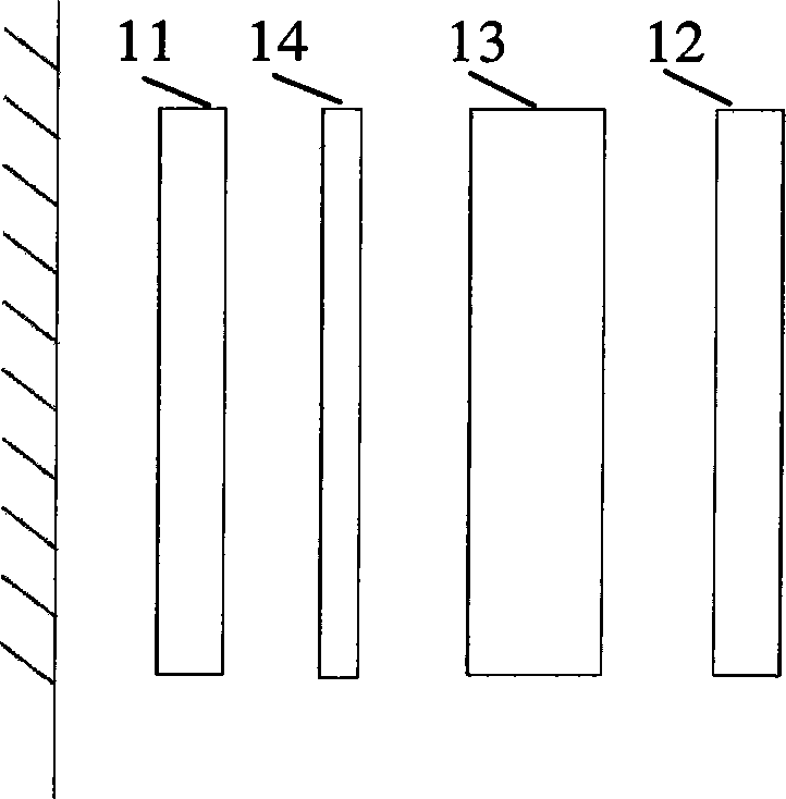
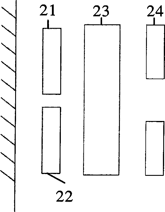
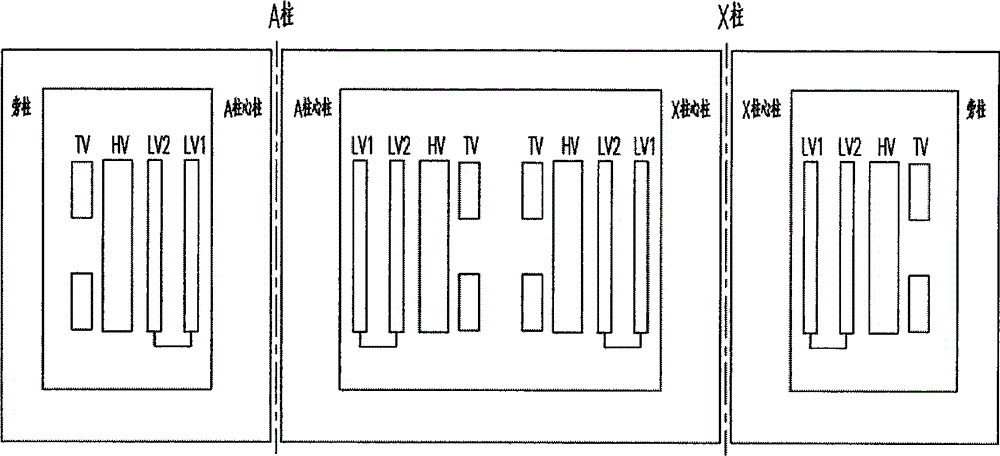
[0037] The split transformer in this embodiment is a single-phase split transformer, specifically, a single-phase two-column parallel-connected double-split transformer. In this embodiment, the split transformer is applied to an ultra-high voltage large-scale transformer of a hydropower station subject to transportation restrictions. In this embodiment, it can be specifically applied to a transformer with a voltage level of 400 kV or 500 kV and above. Together with two generators, it forms a two-machine-one-change split transformer, that is, the low-voltage side of the primary side can be connected to two generators, and the high-voltage side of the secondary side is only led out by one way, so as to increase the voltage of the generator Connect to the grid again. In this embodiment, the capacity of the split transformer is specifically 147MVA.

[0038] Such as image 3 As shown, the split transformer in this embodiment includes an iron core and a winding, and the winding in...


PUM


Abstract

The invention provides a split transformer, which includes an iron core and windings. The windings include a high-voltage winding, a low-voltage winding and a voltage-regulating winding. The iron core adopts a four-column structure, including two core columns and two side columns, and two core columns The winding direction of the upper winding is opposite, and the winding order of the winding on the core column is the low-voltage winding, the high-voltage winding and the voltage-regulating winding from the inside to the outside. The low voltage windings are independent of each other. The body structure of the split transformer is the same as that of the main transformer of an ordinary generator, but it is simpler than the structure using the amplitude split method, which can effectively reduce the transportation cost of the transformer, and the split branch can not only operate in a single branch, but also in double branches. Running, good short-circuit resistance.

Description

technical field [0001] The invention belongs to the technical field of transformer manufacturing, and in particular relates to a split transformer. Background technique [0002] The existing split transformers mainly have two forms: amplitude split and axial split. [0003] figure 1 It is a schematic structural diagram of a transformer winding using amplitude splitting in the prior art. Such as figure 1 As shown, in this winding structure, the winding order of the windings on the iron core from inside to outside is: first low-voltage winding 11-voltage regulating winding 14-high-voltage winding 13-second low-voltage winding 12, wherein the high-voltage winding 13 is located at the first Second, the inner side of the low-voltage winding 12, so the high-voltage winding 13 needs to use the end outlet method. When the transformer adopting this type of winding structure is an ultra-high voltage transformer, because its high-voltage winding 13 generally can only adopt the end-...

Claims


Application Information

Patent Timeline
IPC IPC(8): H01F27/24H01F27/30
Inventor 宁澔如李勇孙树波代斌伍纯红刘金波
Owner TBEA HENGYANG TRANSFORMERS
Why Eureka
Try Eureka