Inverter topology decoupling method and inverter topology decoupling device

A topology structure, inverter technology, applied in output power conversion devices, irreversible DC power input conversion to AC power output, electrical components, etc. Completely decoupled control and other issues

Inactive Publication Date: 2016-06-29
CRRC DALIAN R & D CO LTD
View PDF1 Cites 2 Cited by
  • Summary
  • Abstract
  • Description
  • Claims
  • Application Information

AI Technical Summary

Problems solved by technology

However, this solution uses two capacitors in series, and they must bear the full load phase current in single-phase load, so the capacity of the required capacitor must be large, and when the load changes, the midpoint potential must fluctuate, so it cannot be realized Defects of fully decoupled control, figure 2 Another schematic diagram of the topology of the inverter provided by the prior art, the inverter is a three-phase four-leg inverter, which solves the above problems well, as figure 2 As shown, the fourth bridge arm 2 is connected to the neutral point 3 of the load, which can directly control the neutral current without the need for a large voltage dividing capacitor. The control is flexible and the DC voltage utilization rate is high, and the neutral point forming transformer or Δ / Y transformer can be omitted. Reducing the size and weight of the inverter is a topology that is more suitable for handling unbalanced loads
[0004] However, due to the coupling effect caused by the filter inductance of the fourth bridge arm, the three-phase control becomes very complicated
At present, there is no effective decoupling method to realize the decoupling control of the three-phase four-leg inverter

Method used


Image

  • Inverter topology decoupling method and inverter topology decoupling device
  • Inverter topology decoupling method and inverter topology decoupling device
  • Inverter topology decoupling method and inverter topology decoupling device

Examples


Embodiment Construction

[0049] In order to make the purpose, technical solutions and advantages of the embodiments of the present invention clearer, the technical solutions in the embodiments of the present invention will be clearly and completely described below in conjunction with the drawings in the embodiments of the present invention. Obviously, the described embodiments It is a part of embodiments of the present invention, but not all embodiments. Based on the embodiments of the present invention, all other embodiments obtained by persons of ordinary skill in the art without making creative efforts belong to the protection scope of the present invention.

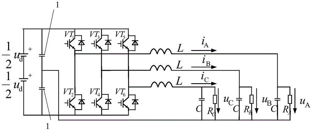
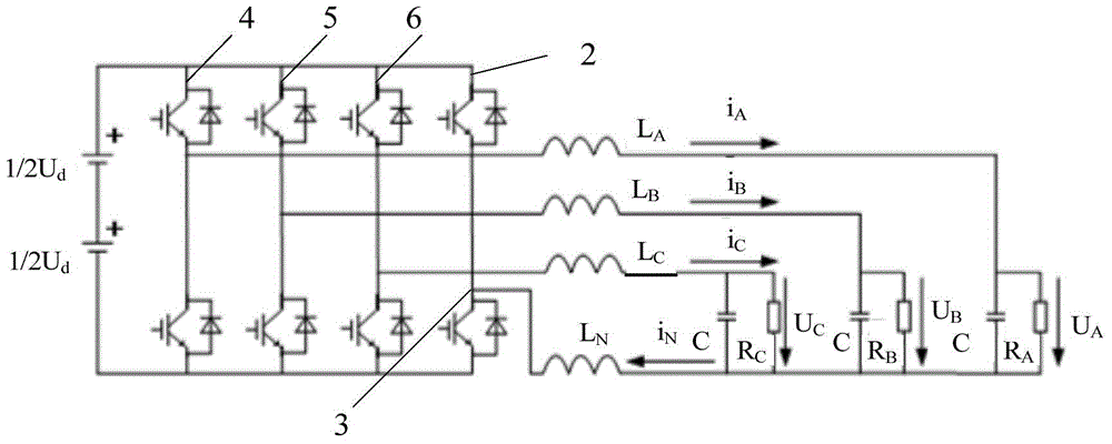
[0050] The present invention takes the three-phase four-leg inverter as an example, as figure 2 As shown, the fourth bridge arm 2 is connected to the load neutral point 3, which can directly control the neutral current. Because the filter inductance of the fourth bridge arm 2 causes the coupling effect with the first bridge arm 4, the secon...


PUM


Abstract

The invention provides an inverter topology decoupling method and an inverter topology decoupling device. The method comprises the following steps: making inverter topology decoupling equivalent to a parallel equivalent circuit of a first circuit, a second circuit, a third circuit and a fourth circuit; determining a coefficient relation according to a loop voltage equation of the parallel equivalent circuit; and making inverter topology decoupling equivalent to a parallel circuit of independent fifth, sixth and seventh circuits according to the coefficient relation. Thus, the output symmetry of three-phase output voltage is kept under three-phase imbalance or nonlinear load, balanced load operation is facilitated, and the harmonic effect of power equipment on the power system is reduced.

Description

technical field [0001] The invention relates to the field of power systems, in particular to a method and device for decoupling an inverter topology. Background technique [0002] Generally, asymmetrical operation is easy to occur in the power system, that is, there are unbalanced loads on the three phases of the inverter, resulting in a large number of harmonics in the power grid. The harm caused by these harmonics is becoming more and more serious, which reduces the efficiency of production, transmission and utilization of electric energy. In severe cases, the equipment may not even work normally. This is especially obvious in industries such as railways and metallurgy. In particular, three-phase unbalanced or nonlinear loads often appear in the inverter load of railway electric locomotives. Sometimes the grid voltage will be severely distorted, the voltage will appear positive and negative half-cycle asymmetry, the waveform will be severely distorted, and the frequency wi...

Claims


Application Information

Patent Timeline
Patent Type & Authority Applications(China)
IPC IPC(8): H02M7/48H02M1/12
Inventor 王乃福徐从谦耿辉李婷婷
Owner CRRC DALIAN R & D CO LTD
Why Eureka
Try Eureka