
Spray nozzle for fluidized catalytic cracking

A technology of spray nozzles and nozzles, which is applied in the field of spray nozzle components, and can solve problems such as erosion, increased cost of nozzle components, and time-consuming

Active Publication Date: 2016-06-29
SPRAYING SYST
View PDF7 Cites 6 Cited by
  • Summary
  • Abstract
  • Description
  • Claims
  • Application Information

AI Technical Summary

Problems solved by technology

Due to the complexity of the nozzle body, this machining is laborious and time consuming and adds significantly to the cost of the nozzle assembly
Furthermore, since the end of the striker pin is placed in the path of travel of the pressurized flow, it is more susceptible to erosion by steam injection, resulting in the need for periodic and costly replacement

Method used


Image

  • Spray nozzle for fluidized catalytic cracking
  • Spray nozzle for fluidized catalytic cracking

Examples


Embodiment Construction

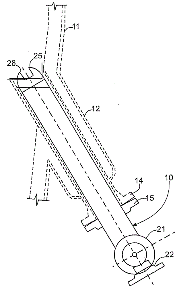
[0012] Referring now more specifically to the drawings, there is shown an exemplary spray nozzle assembly 10 according to the present invention mounted in a conventional manner within an insulating wall 11 (shown in phantom) of a riser of a fluidized catalytic reactor. The spray nozzle assembly 10 is supported within a tubular sleeve 12 secured within the wall 11 at an acute angle to the vertical to discharge atomized liquid hydrocarbons upward into the standpipe. The tubular sleeve 12 has an outwardly extending flange 14 to which a support flange 15 secured to the spray nozzle assembly 10 may be secured.

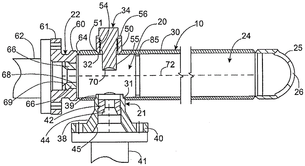
[0013] as in figure 2 As best shown in , the spray nozzle assembly 10 basically includes a mixing zone 20 , an elongated barrel extension 24 communicating with the mixing zone 20 , and a nozzle tip 25 having one or more discharge orifices 26 . The mixing zone 20 has a liquid hydrocarbon inlet 21 and a pressurized steam or gas inlet 22 provided on the outside of the riser ...


PUM


Abstract

A gas assisted spray nozzle assembly having a nozzle body in the form of a one piece hollow tubular member, such as a single cylindrical pipe section, which defines a mixing zone and a downstream barrel extension zone. A liquid inlet and an impingement pin are supported by said tubular member in opposed relation to each other at the mixing zone, and pressurized gas inlet is provided at an upstream end of the tubular member. The impingement pin in this case has an impingement surface radially offset from a central axis of the mixing zone on a side opposite the liquid inlet for receiving pressurized liquid and redirecting the liquid toward the central axis for enhanced intermixing with and atomization by the pressurized gas stream.

Description

[0001] Cross References to Related Applications [0002] This patent application claims the benefit of US Provisional Patent Application No. 61 / 880,268, filed September 20, 2013, which is hereby incorporated by reference. technical field [0003] The present invention relates generally to spray nozzles, and more particularly to spray nozzle assemblies particularly adapted for atomizing and spraying liquid feedstocks into fluidized catalytic cracking riser reactors. Background technique [0004] A spray nozzle assembly of the type described above is shown and described in US Patent No. 5,921,472, the disclosure of which is hereby incorporated by reference. Such spray nozzle assemblies typically include a nozzle body defining a mixing chamber into which liquid hydrocarbons and compressed gas, such as steam, are introduced and where the liquid hydrocarbons are atomized. To enhance atomization of the liquid within the mixing chamber, an impingement pin extends into the chamber ...

Claims


Application Information

Patent Timeline
Patent Type & Authority Applications(China)
IPC IPC(8): B05B7/04
CPCB01J4/002B01J8/1827B01J2208/00902C10G11/18G16B30/00G16B40/00B01J8/24B05B7/0416G06N20/00G06N20/10
Inventor M.拉克罗伊克
Owner SPRAYING SYST
Features
  • Generate Ideas
  • Intellectual Property
  • Life Sciences
  • Materials
  • Tech Scout
  • Unparalleled Data Quality
  • Higher Quality Content
  • 60% Fewer Hallucinations
Learn More