Pulse back blowing dedusting device and gas ejector and filtering device thereof

A technology of pulse blowback and dust removal device, which is applied in the fields of dispersed particle filtration, transportation and packaging, chemical instruments and methods, etc. It can solve the problems of great difference in dust removal effect, difficult removal of dust layer, and more severe vibration of filter tubes, etc. , to avoid the bridging of the dust layer, reduce the risk of thermal shock and fatigue fracture, and achieve the effect of uniform and thorough cleaning

Inactive Publication Date: 2016-07-06
HENAN POLYTECHNIC UNIV
View PDF3 Cites 5 Cited by
  • Summary
  • Abstract
  • Description
  • Claims
  • Application Information

AI Technical Summary

Problems solved by technology

[0008] First of all, in order to effectively clean the filter tube at the edge position inside the ejector, in actual operation, it often needs a back-flush cleaning pressure that is about twice the operating pressure of the filter. The high pressure of back blowing and cleaning will cause the filter tube to be subjected to a great impact force, which will easily cause the filter tube to vibrate during this process. The higher the back blowing and cleaning pressure, the more severe the vibration of the filter tube. The filter tube is damaged or even broken due to thermal shock fatigue
[0009] In addition, during the pulse back blowing, after the transient energy generated by the back blowing air flow enters the filter tube, during the process of energy transfer along the open end of the filter tube to the closed end of the end, the back blowing air flow continuously flows from the filter tube to the closed end of the filter tube. Leakage in the pores of the porous channel makes the energy dissipate continuously during the transfer process, resulting in a great difference in the cleaning effect between the lower part and the upper part of the filter tube. The phenomenon of complete dust removal will cause the dust layer between the filter tubes to bridge, which will easily cause the filter tubes to fail

Method used


Image

  • Pulse back blowing dedusting device and gas ejector and filtering device thereof
  • Pulse back blowing dedusting device and gas ejector and filtering device thereof
  • Pulse back blowing dedusting device and gas ejector and filtering device thereof

Examples


Embodiment Construction

[0028] In order to have a clearer understanding of the technical features, purposes and effects of the present invention, the specific implementation manners of the present invention will now be described in detail with reference to the accompanying drawings.

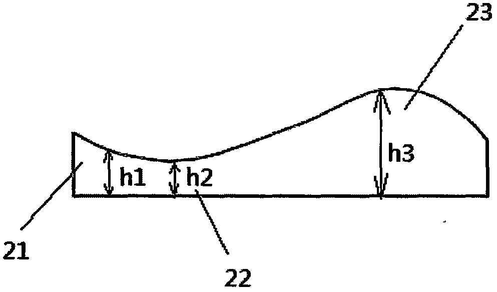
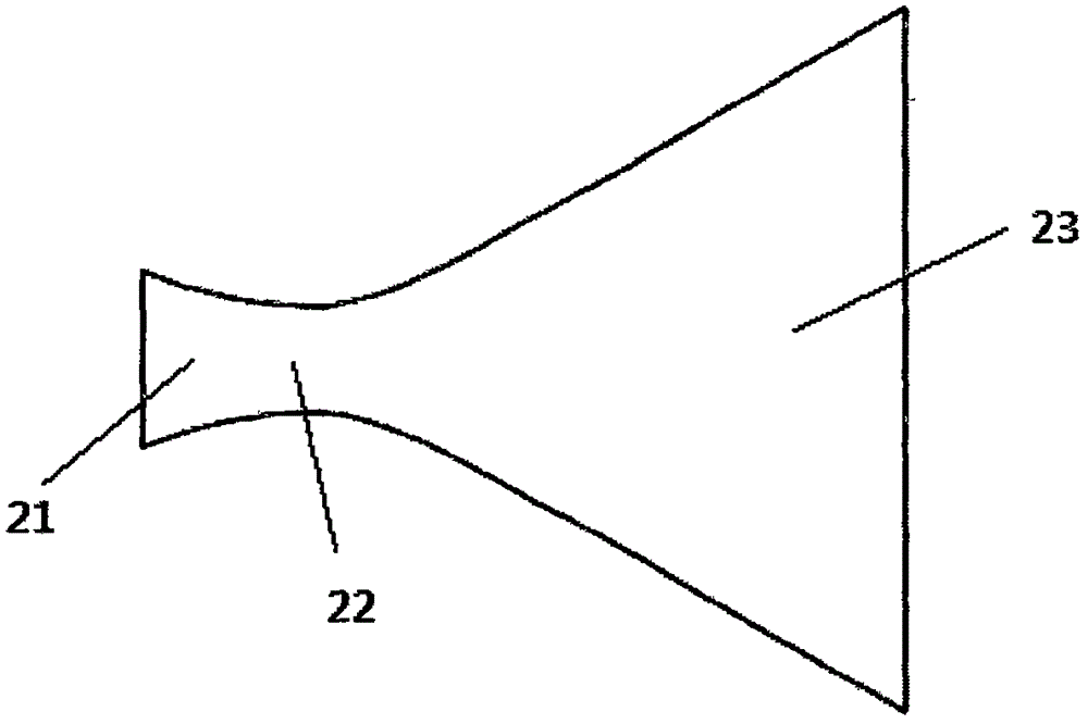
[0029] Figure 2a , 2b and 2c are gas ejectors of a pulse back-flushing soot cleaning device provided by the embodiment of the present invention. The gas ejector includes an ejector body, and the ejector body includes an inlet portion 21, a neck portion 22 and a bow portion 23 connected to each other in sequence, wherein the inlet portion 21, the neck portion 22 and the bow portion 23 are longitudinally sectioned. The heights h1, h2, and h3 of the scale change from large to small and then to large again.

[0030] In this way, from the inlet 21 to the neck 22, the longitudinal section of the gas ejector is reduced from large to small, and when the gas flows through the reduced neck 22, a low-pressure zone is formed tha...


PUM


Abstract

The invention provides a pulse back blowing dedusting device and a gas ejector and filtering device thereof.The gas ejector adopted by the pulse back blowing dedusting device and the filtering device comprises an ejector body.The ejector body comprises an inlet portion, a neck portion and a bow portion which are connected in sequence.The heights of the longitudinal sections of the inlet portion, the neck portion and the bow portion are sequentially decreased and then increased, and the gas ejector is transversely arranged relative to a filter pipe of the filtering device.By improving the shape of the gas ejector and the arrangement mode of the pulse back blowing dedusting device, the filter pipe corresponding to the gas ejector can achieve uniform back blowing, the flow distribution condition of gas blown into the gas ejector is improved, and uniform and thorough dedusting can be performed on the filter pipe.In this way, on the one hand, back blowing dedusting pressure can be lowered, vibration of the filter pipe is reduced, and thermal shock and fatigue crack risks are lowered; on the other hand, dust layer bridging between filter pipes can be avoided, and the phenomenon that filter pipes lose efficacy is avoided.

Description

technical field [0001] The invention belongs to the technical field of gas-solid separation, and relates to a filter device, in particular to a pulse back-blowing soot cleaning device in the filter device and a gas ejector thereof. Background technique [0002] With the deterioration of air quality, more and more attention has been paid to the development of filter materials for high-temperature exhaust gas filtration and emission. In recent years, a large amount of high-temperature industrial waste gas has caused serious pollution to the atmospheric environment. Topics such as "air quality", "smog", and "PM2.5" have rapidly heated up and become hot issues of global concern. [0003] In chemical industry, petroleum, metallurgy, electric power and other industries, high temperature dusty gas is often produced. Because these different processes need to recover energy and meet environmental protection emission standards, it is necessary to remove dust from these high-temperatu...

Claims


Application Information

Patent Timeline
Patent Type & Authority Applications(China)
IPC IPC(8): B01D46/42B01D46/24
CPCB01D46/24B01D46/42B01D46/72B01D46/71
Inventor 李海霞白雪温小萍万剑峰江伟李宾
Owner HENAN POLYTECHNIC UNIV
Why Eureka
Try Eureka