Slag removing mechanism of electrolytic aluminum liquid slag removing machine

A technology of electrolytic aluminum liquid and slag machine, applied in mechanical cleaning, manufacturing tools, metal processing equipment, etc., can solve the problems of waste of manpower, backward production technology, and burns of personnel, and achieve the effect of saving manpower and high production efficiency

Active Publication Date: 2016-07-06
CHONGQING QINENG ELECTRICITY & ALUMINUM
View PDF5 Cites 3 Cited by
  • Summary
  • Abstract
  • Description
  • Claims
  • Application Information

AI Technical Summary

Problems solved by technology

[0003] In the production process of the existing cast aluminum ingots, in order to reduce the content of impurities in the aluminum ingots and form aluminum ingot products with relatively good appearance and high quality, at least 2 employees must be arranged in each shift to carry out manual work uninterruptedly beside the casting line. Slagging operation, the production process is relatively backward, and wastes manpower
Although the slag workers are equipped with safety protection measures such as protective masks during the operation, the occasional high-temperature aluminum water splashed may still cause burns to the personnel. At the same time, the roasting of the high-temperature aluminum water will cause high-temperature radiation to the slag workers, which is not conducive to slag operations. The life and health of slag personnel

Method used


Image

  • Slag removing mechanism of electrolytic aluminum liquid slag removing machine
  • Slag removing mechanism of electrolytic aluminum liquid slag removing machine
  • Slag removing mechanism of electrolytic aluminum liquid slag removing machine

Examples


Embodiment Construction

[0022] The present invention will be further described below in conjunction with the accompanying drawings and specific embodiments, so that those skilled in the art can better understand the present invention and implement it, but the examples given are not intended to limit the present invention.

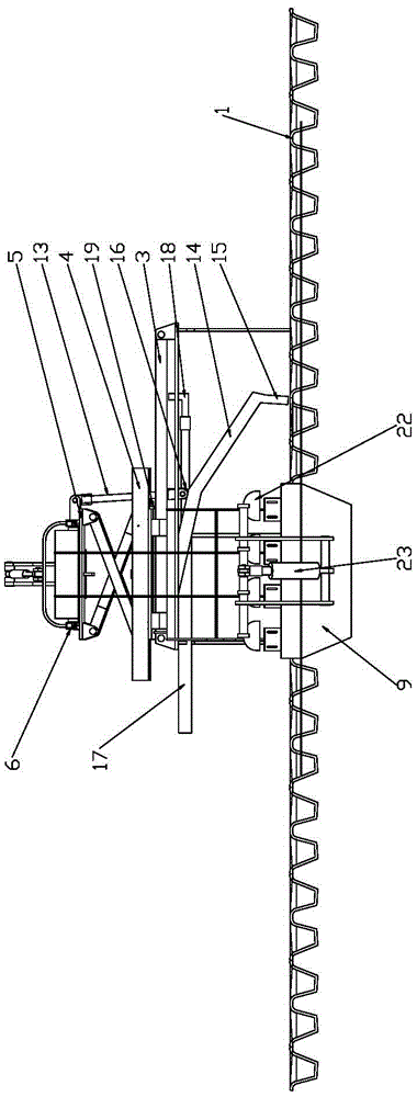
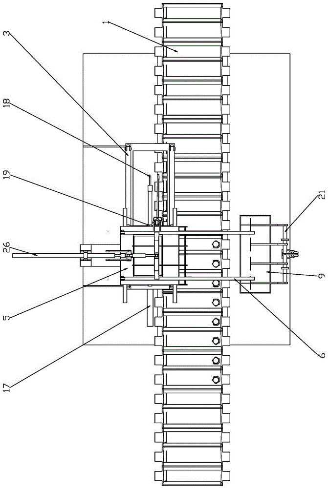
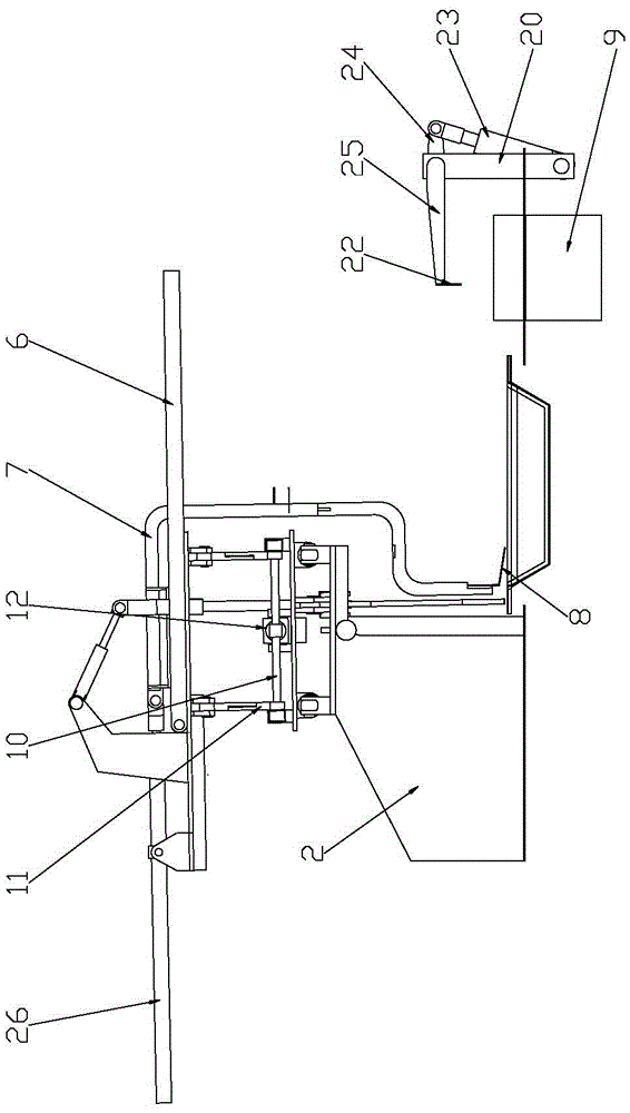
[0023] Such as figure 1 As shown, it is a structural schematic diagram of a slag machine adopting the slag breaking mechanism of the electrolytic aluminum liquid slag machine of the present invention. The slag breaker includes a slag removal mechanism and a slag removal mechanism respectively arranged correspondingly on both sides of the casting mold chain 1 .

[0024] The slagging mechanism of the electrolytic aluminum liquid slag breaking machine in this embodiment includes a fixedly installed mounting frame 2, the mounting frame 2 is provided with a guide rail 3 parallel to the moving direction of the mold chain 1, and a sliding plate 4 is provided on the guide rail 3 to slide ...


PUM


Abstract

The invention discloses a slag removing mechanism of an electrolytic aluminum liquid slag removing machine. The slag removing mechanism comprises a mounting rack arranged on one side of a cast mold chain, wherein a guide rail parallel to the moving direction of the cast mold chain is arranged on the mounting rack; a sliding plate is arranged on the guide rail through sliding matching; a lifting plate is arranged above the sliding plate; a lifting mechanism used for driving the lifting plate to perform rising and falling motions is arranged between the lifting plate and the sliding plate; a synchronous mechanism used for driving the lifting plate to perform synchronous movement with the cast mold chain when the lifting plate is in a low position, and a resetting mechanism used for driving the lifting plate to rest when the lifting plate is in a high position are arranged on the sliding plate; a slide rail vertical to the moving direction of the cast mold chain is arranged on the lifting plate; a slag shoveling device is arranged on the slide rail through sliding matching; the slag shoveling device comprises a slag shoveling plate which stretches into a cast mold of the cast mold chain to perform slag removing operation when the lifting plate is in a low position; and a slag shoveling driving mechanism used for driving the slag shoveling device to perform reciprocating motion along the slide rail is arranged on the lifting plate.

Description

technical field [0001] The invention belongs to the technical field of electrolytic aluminum equipment, and in particular relates to a slagging mechanism of a slag breaking machine for electrolytic aluminum liquid. Background technique [0002] The liquid primary aluminum produced by the aluminum electrolytic cell contains non-metallic solid inclusions, mainly including alumina, carbon, aluminum carbide, etc., among which alumina is the majority. These inclusions will affect the performance of aluminum products. Therefore, before using primary aluminum to produce aluminum ingots or aluminum alloys for remelting, it must be purified to remove solid inclusions in liquid aluminum. [0003] In the production process of existing cast aluminum ingots, in order to reduce the content of impurities in aluminum ingots and form aluminum ingot products with relatively good appearance and high quality, at least 2 employees must be arranged in each shift to carry out manual work uninterru...

Claims


Application Information

Patent Timeline
Patent Type & Authority Applications(China)
IPC IPC(8): B22D43/00C25C3/06
CPCB22D43/007C25C3/06
Inventor 易智民刘伟明钟光军黄安宁李海民李健李宇翱李家义王精兵池有明
Owner CHONGQING QINENG ELECTRICITY & ALUMINUM
Why Eureka
Try Eureka