Winding device for active optical fiber and fiber winding method

An optical fiber and winding technology, which is applied in the field of high-power fiber lasers or fiber amplifiers, can solve the problems that a certain compressive stress is easily generated at the fixed place, affects the uniformity of fiber heat dissipation, and affects the stability of output light, so as to reduce the difference in winding diameter. , maintain natural stretch, optimize the effect of output beam quality

Inactive Publication Date: 2016-07-06
JIANGSU SKYERALASER TECH
View PDF7 Cites 8 Cited by
  • Summary
  • Abstract
  • Description
  • Claims
  • Application Information

AI Technical Summary

Problems solved by technology

[0002] During the working process of high-power fiber laser or fiber amplifier, the doped ions in the active fiber absorb the pump light to excite the output laser of the corresponding wavelength. During the excitation process, a considerable part of the energy is generated in the fiber in the form of heat. In the fiber If the heat accumulated in the battery cannot be dissipated in time, it will affect the stability of the output light and even burn out the optical fiber
At present, there are two main ways to coil the active optical fiber: one method is to coil the active optical fiber on a smooth aluminum plate, and realize the heat dissipation of the active optical fiber through the close fit of the optical fiber and the aluminum plate. In the process of coiling the optical fiber, it is easy to cause crossing and overlapping of the optical fiber to cause uneven heat dissipation. At the same time, it is difficult to fix the entire optical fiber reel after the optical fiber is coiled, and a certain compressive stress is likely to be generated at the fixing point, which affects the uniformity of the optical fiber heat dissipation; another One method is to coil the active optical fiber on a smooth cylinder or cone, avoiding the staggered overlap of the optical fiber during the coiling process, and realizing uniform heat dissipation of the optical fiber, but in order to ensure the tight combination of the optical fiber and the cylinder or Give the fiber a certain tension during the coiling process, and the internal stress of the entire fiber will affect the stability of long-term work

Method used


Image

  • Winding device for active optical fiber and fiber winding method
  • Winding device for active optical fiber and fiber winding method
  • Winding device for active optical fiber and fiber winding method

Examples


Embodiment Construction

[0016] In order to make the content of the present invention more clearly understood, the present invention will be further described in detail below based on specific embodiments and in conjunction with the accompanying drawings.

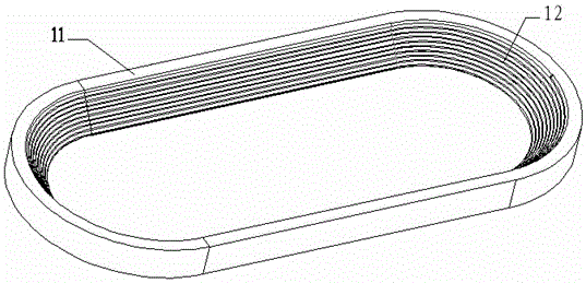
[0017] like Figure 1~3 As shown, a coiling device for active optical fiber, it includes a body, the body has:

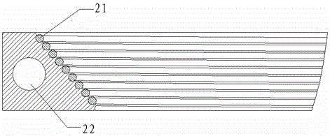
[0018] The heat dissipation disk 11, the heat dissipation disk 11 is a racetrack structure, and the inner wall surface of the heat dissipation disk 11 is a slope, and the inner wall slope of the heat dissipation disk 11 is provided with a container for attaching the optical fiber 21 to the heat dissipation disk 11. There is a space between adjacent turns of the optical fiber 21 on the housing structure.

[0019] like Figure 1~3 As shown, the accommodating structure is a semicircular groove 12 arranged on the inclined surface of the inner wall and coiled from bottom to top, and the diameter of the semicircular groove 12 and the optical...


PUM


Abstract

The invention discloses a winding device for an active optical fiber and a fiber winding method. The winding device for the active optical fiber comprises a heat dissipation disk, wherein the heat dissipation disk adopts a track structure, the inner wall of the heat dissipation disk is an inclined surface, a groove for winding the active optical fiber is formed in the inclined surface, and the adjacent groove parts are spaced by a certain interval. With the adoption of the winding device and the fiber winding method, heat of the active optical fiber can be better dissipated, besides, the optical fiber extends naturally in the winding process so as to avoid pressure stress caused by fixation by the aid of external force, meanwhile, the difference of inner and outer winding diameters of the optical fiber is small, high-order mode lasers are effectively filtered out, and near-fundamental-mode laser output with the high laser beam quality is obtained.

Description

technical field [0001] The invention relates to a winding device and a fiber winding method for active optical fibers, mainly used for high-power fiber lasers or fiber amplifiers. Background technique [0002] During the working process of high-power fiber laser or fiber amplifier, the doped ions in the active fiber absorb the pump light to excite the output laser of the corresponding wavelength. During the excitation process, a considerable part of the energy is generated in the fiber in the form of heat. In the fiber If the heat accumulated in the optical fiber cannot be dissipated in time, it will affect the stability of the output light and even burn out the optical fiber. At present, there are two main ways to coil the active optical fiber: one method is to coil the active optical fiber on a smooth aluminum plate, and realize the heat dissipation of the active optical fiber through the close fit of the optical fiber and the aluminum plate. In the process of coiling the...

Claims


Application Information

Patent Timeline
Patent Type & Authority Applications(China)
IPC IPC(8): B65H75/16
CPCB65H75/16B65H2701/32Y02P70/10
Inventor 席道明陈云马永坤吕艳钊魏皓
Owner JIANGSU SKYERALASER TECH
Why Eureka
Try Eureka