Working device lifting and swinging connecting frame device used on roadside stone cleaning machine

A working device and swing connection technology, applied in road cleaning, cleaning methods, construction, etc., can solve problems such as abnormal work, high labor intensity, and potential safety hazards, and achieve the effects of simple structure, convenient maintenance, and easy disassembly

Active Publication Date: 2016-07-06
王海维
View PDF9 Cites 8 Cited by
  • Summary
  • Abstract
  • Description
  • Claims
  • Application Information

AI Technical Summary

Problems solved by technology

[0002] In sanitation work, the cleaning of roadside stones is mostly done by manual scrubbing, which is labor-intensive and has potential safety hazards, which adds a lot of burden to sanitation workers
In recent years, the invention of the roadside stone cleaning machine (patent has been declared) has solved this problem very well, but the road conditions and the driver's operation (not necessarily driving in a straight line or under special circumstances) are affected by the roadside stone cleaning machine. To the left or right) is very demanding, on the road with obstacles can not continue to work over obstacles, also easy to damage the machine parts and not work properly on slopes and curves

Method used


Image

  • Working device lifting and swinging connecting frame device used on roadside stone cleaning machine
  • Working device lifting and swinging connecting frame device used on roadside stone cleaning machine
  • Working device lifting and swinging connecting frame device used on roadside stone cleaning machine

Examples


Embodiment Construction

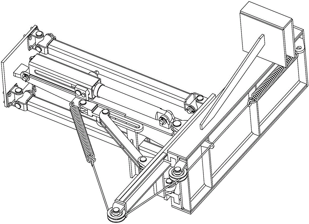
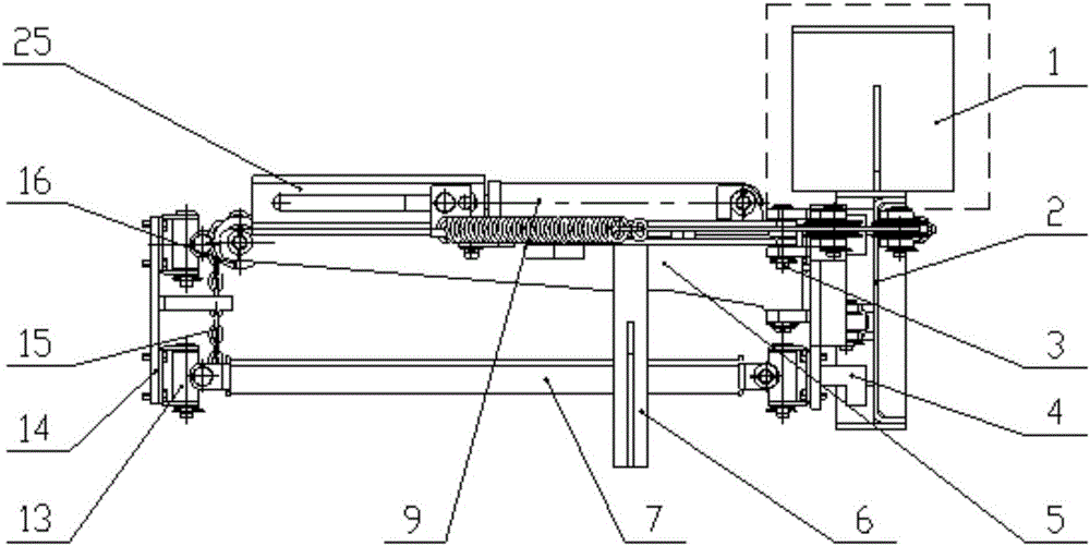
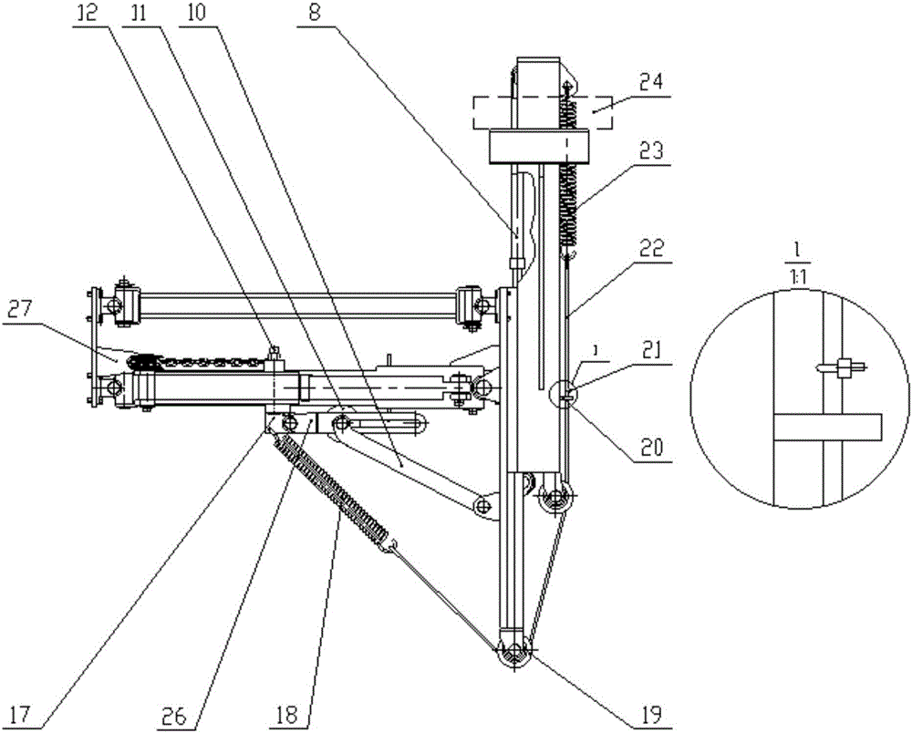
[0023] The following is attached figure 1 The given embodiment further describes in detail the lifting and swinging connecting frame device of the working device used on the curb cleaning machine of the present invention.

[0024] refer to Figure 1 to Figure 5 , a lifting and swinging connecting frame device for a working device on a curb cleaning machine, including a main connecting plate 1, a side vertical plate assembly 2, a main sliding vertical plate assembly 4, a horizontal swing arm assembly 5, and left and right limiters Plate 6, lifting swing connecting rod 7, side telescopic oil cylinder 8, lifting swing oil cylinder 9, auxiliary pull rod 10, connecting plate 14 of cleaning working device, chain 15, guide wheel 16, connecting slider 17, auxiliary tension spring 18, fixed pulley 19 , limit plate 20, limit fixed block 21, steel wire rope 22, preload spring 23, limit square tube 25, limit groove plate 26, chain limit plate 27.

[0025] The main connecting plate 1 is ...


PUM


Abstract

The invention discloses a rolling brush work lifting and swinging connecting frame device used on a roadside stone cleaning machine. A side vertical plate assembly is vertically welded with a main connecting plate; a main sliding vertical plate assembly is in sliding connection with the inner side wall of the side vertical plate assembly through a side telescopic oil cylinder; one end of a lifting and swinging oil cylinder is connected with the upper plane of a horizontal swinging arm assembly, and the other end of the lifting and swinging oil cylinder is connected with a limit sliding mechanism; one end of an auxiliary pull rod is hinged to a limit groove plate, and the other end of the auxiliary pull rod is hinged to the main sliding vertical plate assembly; one end of an auxiliary tension spring is hinged to the limit sliding mechanism, and the other end of the auxiliary tension spring is connected with the front end of a pre-tightening tension spring through a steel wire rope; the tail end of the pre-tightening tension spring is connected with the side vertical plate assembly; a cleaning working device connecting plate is hinged to the main sliding vertical plate assembly through a lifting and swinging connecting rod. The device is mounted on the roadside stone cleaning machine, so that a working device of the roadside stone cleaning machine can realize the extension and the lifting from the side surface of a main vehicle frame; meanwhile, the steel wire rope for swinging the tension spring is always in a stretched state to achieve the purposes that the working device efficiently works, and the cleaning effect is good.

Description

technical field [0001] The invention relates to a roller brush lifting multi-link linkage connecting frame device on a roadside stone cleaning machine, in particular to a rolling brush working lifting and swinging connecting frame device used on a roadside stone cleaning machine. Background technique [0002] In sanitation work, the cleaning of roadside stones is mostly done by manual scrubbing, which is labor-intensive and has potential safety hazards, which adds a lot of burden to sanitation workers. In recent years, the invention of the roadside stone cleaning machine (patent has been declared) has solved this problem very well, but the road conditions and the driver's operation (not necessarily driving in a straight line or under special circumstances) are affected by the roadside stone cleaning machine. To the left or to the right) the requirements are very high, and it is impossible to continue to work over obstacles on the road with obstacles, and it is also easy to d...

Claims


Application Information

Patent Timeline
Patent Type & Authority Applications(China)
IPC IPC(8): E01H1/00
CPCE01H1/003
Inventor 王海维
Owner 王海维
Why Eureka
Try Eureka