An axial flow fan with blades with airfoil deflectors and guide vanes with bionic trailing edges

A deflector and vane technology, which is applied in the field of axial flow fans, can solve problems such as exhaust noise, and achieve the effects of reducing noise, thinning the boundary layer, and reducing eddy current noise

Active Publication Date: 2017-12-12
嘉兴芸诗娇电子商务有限公司
View PDF6 Cites 4 Cited by
  • Summary
  • Abstract
  • Description
  • Claims
  • Application Information

AI Technical Summary

Problems solved by technology

If the fan outlet is directly discharged into the atmosphere, there will be exhaust noise

Method used


Image

  • An axial flow fan with blades with airfoil deflectors and guide vanes with bionic trailing edges
  • An axial flow fan with blades with airfoil deflectors and guide vanes with bionic trailing edges
  • An axial flow fan with blades with airfoil deflectors and guide vanes with bionic trailing edges

Examples


Embodiment Construction

[0016] The present invention will be further described below in conjunction with the accompanying drawings and embodiments.

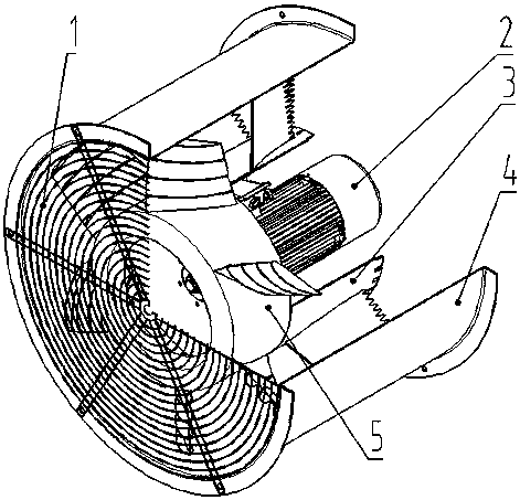
[0017] Such as figure 1 As shown, the axial flow fan is composed of 5 parts, including 1. a net cover, 2. a motor, 3. a guide vane impeller, 4. an outer cylinder, 5. an impeller; the guide vane impeller 3 and the outer cylinder 4 are fixed together, The motor 2 is fixed on the web plate of the inner cylinder of the guide vane impeller 4, and the working parameter of the motor 2 is 720r / min, and the power is 4KW; The gap is 10mm; the net cover 1 is installed on the outer cylinder, which has the functions of rectifying and preventing foreign matter from entering.

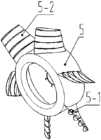
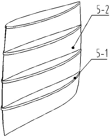
[0018] Such as figure 1 , 2 As shown in , 3 and 4, the impeller 5 is driven by the motor 2 to do work for the gas to increase the dynamic pressure and static pressure of the gas. The blade 5-2 on the impeller 5 is a circular arc plate blade designed by the equal circulation isolated airfoil ...


PUM


Abstract

The invention discloses an axial flow fan with airfoil deflectors on the blades and bionic trailing edges on the guide vanes. Four deflectors are evenly added to the impeller blades of the axial flow fan, and the relative height of the blades is The positions are respectively at 25%, 50%, 75% and leaf top. The airfoil deflector is obtained by keeping the center arc of the blade at each deflector position unchanged, and then superimposing the NACA four-digit airfoil thickness distribution. The airfoil deflector can make the fluid flow in the impeller more stable, the boundary layer is thinner, the fan efficiency is improved, the leakage loss is reduced and the eddy current noise is reduced. The deflector at the tip of the blade can effectively improve the leakage flow at the tip of the blade due to its large area and forms a complex vortex in the gap of the tip of the blade. Through three modifications of this type of fan, the efficiency of the fan can be improved and the noise of the fan can be reduced, so as to achieve the purpose of energy saving and environmental protection.

Description

technical field [0001] The invention belongs to the technical field of axial flow fans, in particular to an axial flow fan with blades with airfoil deflectors and guide vanes with bionic trailing edges. Background technique [0002] The axial flow fan is a machine that relies on the input mechanical energy to increase the gas pressure and discharge the gas. It is widely used in ventilation, dust extraction and cooling of factories, mines, tunnels, cooling towers, vehicles, ships and buildings; ventilation and induction of boilers and industrial furnaces; cooling and ventilation in air conditioning equipment and household appliances ; Grain drying and selection; wind tunnel wind source and hovercraft inflation propulsion, etc., have very important applications in various industries of the national economy. According to statistics, the power consumption of fans accounts for about 10% of the country's power generation, and the average power consumption of main coal mines accou...

Claims


Application Information

Patent Timeline
Patent Type & Authority Patents(China)
IPC IPC(8): F04D25/08F04D29/38F04D29/32F04D29/54F04D29/68F04D29/70
CPCF04D25/08F04D29/329F04D29/384F04D29/388F04D29/541F04D29/681F04D29/703
Inventor 窦华书许文倩徐金秋贾会霞姜陈锋李昆航陈小平魏义坤杨徽
Owner 嘉兴芸诗娇电子商务有限公司
Why Eureka
Try Eureka