Probe of eddy current sensor and eddy current sensor

An eddy current sensor and cable technology, which is applied in the direction of instruments, electric devices, and electromagnetic means, etc., can solve the problem that the sensor cannot accurately reflect the measured displacement, the sensor probe cannot withstand high temperature, unfavorable installation and displacement Detection and other problems, to achieve the effect of eliminating the influence of eddy current field, wide temperature compensation range, and reducing the size of the probe

Active Publication Date: 2016-07-06
GREE ELECTRIC APPLIANCES INC
View PDF6 Cites 6 Cited by
  • Summary
  • Abstract
  • Description
  • Claims
  • Application Information

AI Technical Summary

Problems solved by technology

When the ambient temperature of the sensor exceeds the normal working temperature of the sensor, not only the material of the sensor probe cannot withstand the high temperature, but also the high temperature environment will cause obvious changes in the resistance, inductance and geometric dimensions of the sensor, resulting in the output of the eddy current displacement sensor Can not accurately reflect the size of the measured displacement
[0004] At present, the temperature compensation of eddy current displacement sensors on the market is carried out in the pre-processor for algorithm compensation, and the compensation accuracy of this method is low
In addition, there are many sensors on the market that use some technical measures at the head of the sensor to reduce the influence of the ambient temperature on the electrical parameters of the sensor, such as using multi-strand braided wires or winding coils with low temperature coefficient wires. The compensation effect is limited
In addition, in the prior art, there is also a solution to compensate the detection coil of the sensor to reduce the influence of the ambient temperature on the output characteristics of the coil, such as using a non-inductive compensation coil or using a negative temperature coefficient resistor to compensate the coil temperature. The size of the probe designed by the method will become longer, which is not conducive to installation and displacement detection in some cases

Method used


Image

  • Probe of eddy current sensor and eddy current sensor
  • Probe of eddy current sensor and eddy current sensor
  • Probe of eddy current sensor and eddy current sensor

Examples


Embodiment 1

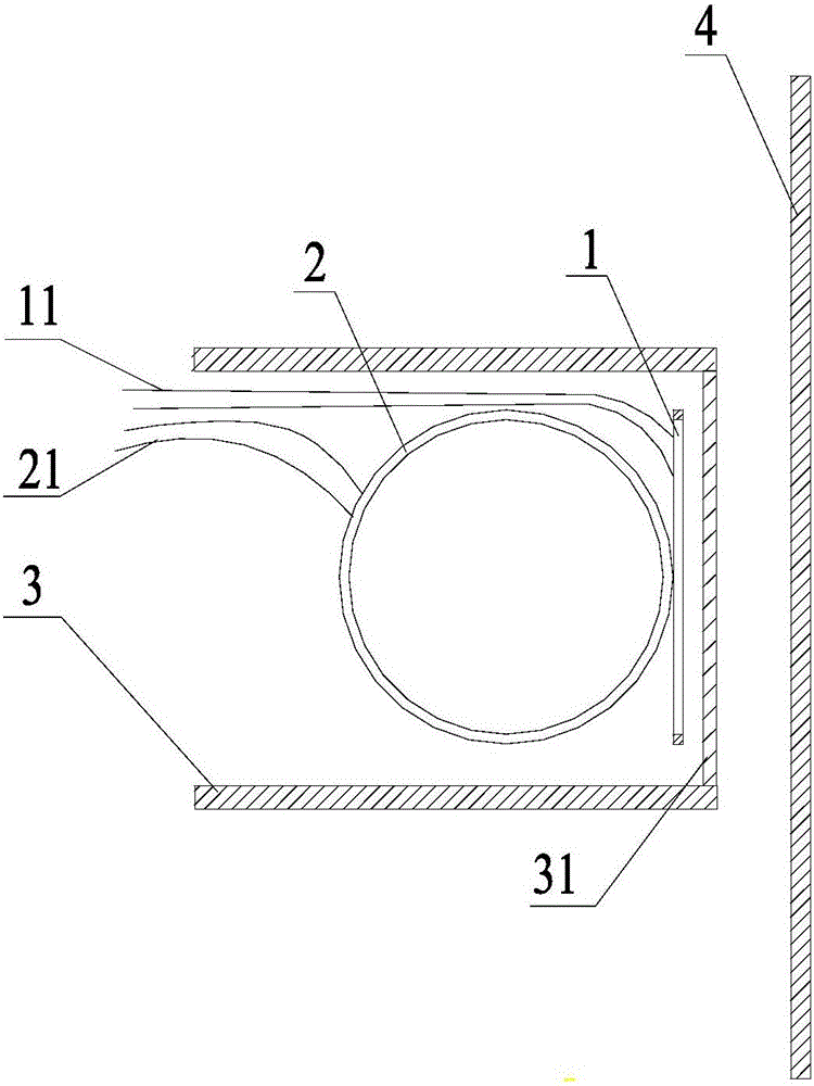
[0022] figure 1 This is a schematic plan view of a probe of an eddy current sensor provided in the first embodiment of the present invention. This embodiment may be suitable for reducing the size of the probe on the basis of ensuring the detection accuracy, and specifically includes: a detection coil 1 and a temperature compensation coil 2. The detection coil 1 is parallel to the detection surface 31 of the probe 3, and the temperature compensation coil 2 is perpendicular to the detection coil 1 and does not exceed the plane of the inner coil of the detection coil 1, wherein the inner side of the detection coil 1 The coil is a one-turn detection coil with the shortest distance from the detection surface 31.

[0023] According to Faraday’s law of electromagnetic induction, when the detection coil 1 in the probe 3 passes through a sinusoidal alternating current i 1 When the space around the detection coil 1 inevitably produces a sinusoidal alternating magnetic field H 1 , It makes t...

Embodiment 2

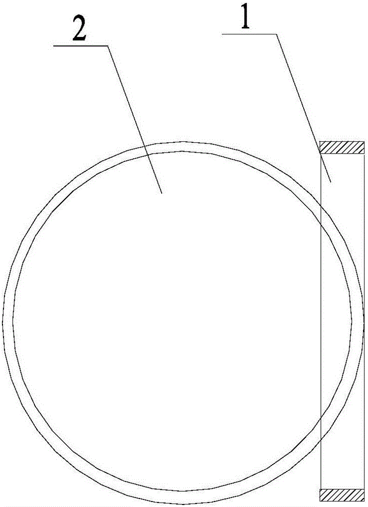
[0029] image 3 It is a schematic plan view of the probe of an eddy current sensor in the second embodiment of the present invention. The technical solution of this embodiment specifically limits the positions of the detection coil 1 and the temperature compensation coil 2 on the basis of the foregoing embodiment, specifically including: the outlines of the detection coil 1 and the temperature compensation coil 2 are both circular , The diameter of the inner coil of the detection coil 1 is tangent to the outer contour of the temperature compensation coil 2. The advantage of this design is to eliminate the influence of the temperature compensation coil 2 on the eddy current field of the detection coil 1 while reducing the size of the probe.

Embodiment 3

[0031] Figure 4 It is a schematic plan view of a probe of an eddy current sensor in the third embodiment of the present invention. The technical solution of this embodiment specifically limits the positions of the detection coil 1 and the temperature compensation coil 2 on the basis of the first embodiment, specifically including: the contours of the detection coil 1 and the temperature compensation coil 2 are both circular , The diameter of the inner coil of the detection coil 1 is separated from the outer contour of the temperature compensation coil 2, and the diameter of the outer coil of the detection coil 1 intersects the outer contour of the temperature compensation coil 2, wherein The outer coil of the detection coil 1 is the one-turn detection coil that is the farthest from the detection surface. The advantage of this design is to eliminate the influence of the temperature compensation coil 2 on the eddy current field of the detection coil 1 while reducing the size of ...


PUM


Abstract

The invention discloses a probe of an eddy current sensor and an eddy current sensor. The probe of the eddy current sensor comprises a detection coil and a temperature compensating coil. The detection coil is in parallel with the test surface of the probe; the temperature compensation coil is perpendicular to the detection coil and does not exceed the plane where the inner side coil of the detection coil is positioned; the inner side coil of the detection coil is a turn of a detection coil having a shortest detection distance with the detection surface. The probe of the eddy current sensor and the eddy current sensor solve the problems that the eddy current sensor in the prior art is not high in detection accuracy because of temperature drift or the probe is large in size because of the temperature compensation, realize the probe size reduction on the basis of the guaranteed accuracy, achieve wide temperature compensation range and small probe size.

Description

Technical field [0001] The embodiment of the present invention relates to a distance measuring device, in particular to a probe of an eddy current sensor and an eddy current sensor. Background technique [0002] The eddy current displacement sensor has many advantages such as non-contact, large measurement range, high sensitivity, simple structure, and is not affected by non-metallic materials, and has been widely used in the detection field. [0003] The probe of an ordinary eddy current displacement sensor is composed of a flat coil and a non-metallic frame with a fixed coil. Since the coil and skeleton usually use common materials, if the ambient temperature of the sensor probe does not change much, the output of the sensor will be less affected by the temperature, and the output of the sensor can accurately reflect the magnitude of the measured displacement. When the ambient temperature of the sensor exceeds the normal working temperature of the sensor, not only the material o...

Claims


Application Information

Patent Timeline
Patent Type & Authority Applications(China)
IPC IPC(8): G01B7/02
CPCG01B7/02
Inventor 刘志昌黄伟才耿继青
Owner GREE ELECTRIC APPLIANCES INC
Why Eureka
Try Eureka