
Turbine tester

A testing device and turbine technology, which is used in measurement devices, engine testing, and machine/structural component testing. The number of iterations, the accuracy of test data, and the effect of saving R&D costs

Active Publication Date: 2016-07-06
TSINGHUA UNIV
View PDF5 Cites 12 Cited by
  • Summary
  • Abstract
  • Description
  • Claims
  • Application Information

AI Technical Summary

Problems solved by technology

At present, foreign engine companies determine the turbine blade life design based on the core machine test, which not only still differs greatly from the turbine blade environment when the real gas turbine is working, resulting in large errors in the turbine blade life design and low blade reliability; moreover, in the core machine test Full-ring blades need to be processed, the quantity is large, the construction period is long, and the cost is expensive. Once a blade problem is found and needs to be modified, the impact will be huge, resulting in a longer design cycle and consuming a lot of development costs.

Method used


Image

  • Turbine tester

Examples


Embodiment Construction

[0021] The turbine testing device provided by the present invention will be further described in detail below in conjunction with the drawings and specific embodiments.

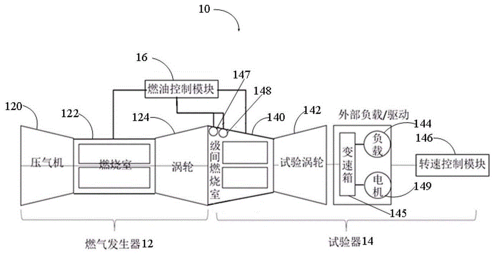
[0022] see figure 1 , The turbine testing device 10 provided by the embodiment of the present invention includes: a gas generator 12 , a tester 14 and a fuel control module 16 . The gas generator 12 includes: a compressor 120 , a combustion chamber 122 and a working turbine 124 . The tester 14 at least includes: an interstage combustion chamber 140 and a test turbine 142 . The interstage combustion chamber 140 is arranged behind the gas generator 12 , so that the high temperature and high pressure gas in the combustion chamber 122 can enter the interstage combustion chamber 140 after passing through the working turbine 124 . The test turbine 142 is arranged behind the interstage combustion chamber 140 , so that the high temperature and high pressure gas in the interstage combustion chamber 140 can flow thro...


PUM


Abstract

The invention relates to a turbine tester which comprises a combustion gas generator including a compressor, a combustion chamber and a working turbine, and a fuel control module. The turbine tester further comprises a tester including an interstage combustion chamber and a tested turbine. The interstage combustion chamber is arranged behind the combustion gas generator, so that the high temperature high pressure gas in the combustion chamber flows by the working turbine and enters into the interstage combustion chamber. The tested turbine is arranged behind the interstage combustion chamber, the high temperature high pressure combustion gas of the interstage combustion chamber flows by the tested turbine and pushes the test turbine to rotate. The combustion gas generator is decoupled from the test turbine.

Description

technical field [0001] The invention relates to the field of turbine engines, in particular to a turbine test device for the turbine engine. Background technique [0002] The working principle of a turbine engine (including turbine aeroengine and turbine gas turbine) is to compress the air to a high-pressure state through the compressor and enter the combustion chamber, mix and burn the injected fuel in the combustion chamber to form high-temperature and high-pressure gas, and then drive the turbine to rotate to do work, thereby Convert fuel chemical energy into mechanical energy. In the process of doing work, the turbine blades of the gas turbine play an important role, which converts the available heat energy of the gas into turbomechanical work. As one of the key components of a gas turbine, the working environment of the turbine blade is quite harsh, and it rotates at high speed under high temperature and high pressure conditions. The high-speed rotation of the blades ...

Claims


Application Information

Patent Timeline
Patent Type & Authority Applications(China)
IPC IPC(8): G01M15/00
CPCG01M15/00
Inventor 袁荒杨俊杰
Owner TSINGHUA UNIV
Learn More