Measurement Method of Harmonic Impedance of Traction Power Supply System

A traction power supply system, harmonic impedance technology, applied in the direction of measuring resistance/reactance/impedance, measuring devices, measuring electrical variables, etc., can solve problems such as lightning arrester and other equipment burning, resonance overvoltage, explosion, etc., to reduce purchase and operation Cost reduction, reduced operating voltage, and accurate measurement results

Active Publication Date: 2019-03-22
SOUTHWEST JIAOTONG UNIV
View PDF3 Cites 0 Cited by
  • Summary
  • Abstract
  • Description
  • Claims
  • Application Information

AI Technical Summary

Problems solved by technology

When the frequency of the harmonic current of the electric locomotive or EMU in the traction power supply system coincides with the resonant frequency of the traction network itself in the section (usually a power supply arm), high-order harmonic resonance may be excited on the traction network. Generate resonant overvoltage or overcurrent, affecting power supply safety
Many harmonic resonance accidents have occurred on site, resulting in overvoltage protection action, tripping of circuit breakers, burnout and even explosion of protectors, lightning arresters and other equipment, and failure of normal operation of parallel compensation devices, seriously affecting the reliability of power supply and the safe operation of high-speed railways
[0003] Due to the complex structure of the traction network, variable operating conditions, and unknown internal component parameters, even if the basic information of the electrified railway traction power supply system is mastered in detail, it is still impossible to calculate the traction network of each section through theoretical calculations. resonant frequency of

Method used


Image

  • Measurement Method of Harmonic Impedance of Traction Power Supply System

Examples


Embodiment

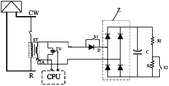
[0027] figure 1 It is shown that a specific embodiment of the present invention is a device for measuring harmonic impedance of a traction power supply system, which is composed of:

[0028] The two ends of the primary coil of the step-down transformer ST are respectively connected with the catenary CW and the rail R of the power supply section, and the current sensor TA is connected in series on the secondary coil, and the two ends of the secondary coil are connected in parallel with the voltage sensor TV; the current sensor TA The output ends of the voltage sensor and the TV are connected to the data processor CPU; the two ends of the secondary coil are also connected to the two output ends of the harmonic current source injection device; wherein, the specific composition of the harmonic current source injection device is:

[0029] One AC terminal of the bridge rectifier circuit Z is directly used as an output terminal of the harmonic current source injection device, the other...


PUM


Abstract

A device for measuring harmonic impedance of a traction power supply system and its measuring method. The device is composed of: the primary side coil of a step-down transformer is connected with the catenary in the power supply section and the rail; the secondary side coil is connected with current and voltage sensors; It is connected with the harmonic current source injection device; the composition of the harmonic current source injection device is: one AC terminal of the bridge rectifier circuit is directly used as an output terminal of the harmonic current source injection device, and the other AC terminal of the bridge rectifier circuit is connected to The cathode of the diode, the anode of the diode is the other output end of the harmonic injection device; the switch is connected between the anode and cathode of the diode; the two DC terminals of the bridge rectifier circuit are connected in parallel with capacitors, and the first and second resistors are connected in parallel to the two DC terminals of the bridge rectifier circuit , the resistor two is connected in parallel with the switch two. The device can measure the resonant frequency of the power supply section and the impedance frequency characteristics of the electric locomotive or EMU in operation, so as to provide more accurate and reliable measured parameters for the design, operation and maintenance of the traction power supply system.

Description

technical field [0001] The invention relates to a method for measuring harmonic impedance of a traction power supply system. Background technique [0002] In recent years, China's high-speed railway has been in a leading position in many aspects, but at the same time, technical standards are also improving, and there are correspondingly higher requirements for the safety and reliability of power supply equipment. When the frequency of the harmonic current of the electric locomotive or EMU in the traction power supply system coincides with the resonant frequency of the traction network itself in the section (usually a power supply arm), high-order harmonic resonance may be excited on the traction network. Generate resonance overvoltage or overcurrent, affecting power supply safety. A number of harmonic resonance accidents have occurred on site, resulting in overvoltage protection actions, tripping of circuit breakers, burnout and even explosion of protectors, lightning arres...

Claims


Application Information

Patent Timeline
Patent Type & Authority Patents(China)
IPC IPC(8): G01R27/14
CPCG01R27/14
Inventor 胡海涛张权何正友马晓兰
Owner SOUTHWEST JIAOTONG UNIV
Why Eureka
Try Eureka