A continuous plate drawing system for a filter press

A filter press and filter plate technology, which is applied in the fields of papermaking, brewing, and sludge treatment industrial equipment manufacturing, can solve the problems of difficult maintenance, high energy consumption, and large space occupation, so as to achieve easy popularization and use, and solve the problem of filter plate sandwiching , the effect of simple structure

Active Publication Date: 2019-05-10
王军
View PDF6 Cites 0 Cited by
  • Summary
  • Abstract
  • Description
  • Claims
  • Application Information

AI Technical Summary

Problems solved by technology

The disadvantage is that every time the plate is pulled, all the filter plates are pulled apart at once, which requires a lot of force to pull apart, so only hydraulic cylinders and piston rods can be used, which is slow and consumes a lot of energy; after all the filter plates are pulled apart, it takes up The space is large, so in order to control the space occupied by the equipment, the design of the number of filter plates is greatly limited. Fewer filter plates means lower production capacity. The same production capacity requires more filter presses, which virtually increases investment and site occupancy.
Moreover, a pull plate type filter press (CN 2817948 Y) has a complex structure, many moving parts, and difficult maintenance

Method used


Image

  • A continuous plate drawing system for a filter press
  • A continuous plate drawing system for a filter press
  • A continuous plate drawing system for a filter press

Examples


Embodiment Construction

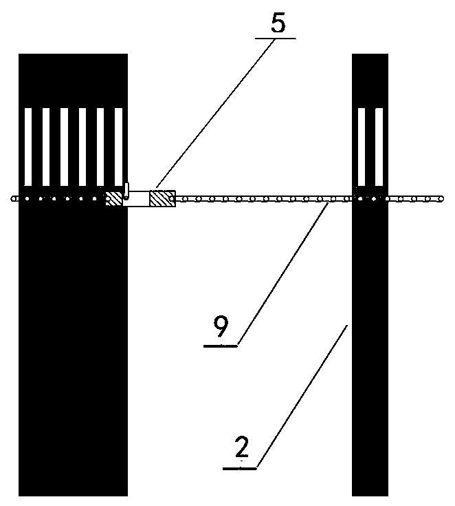
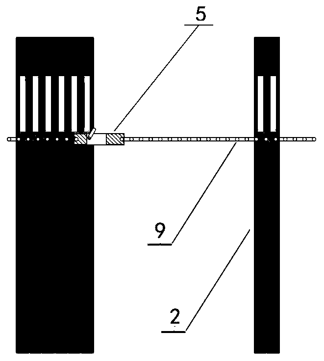
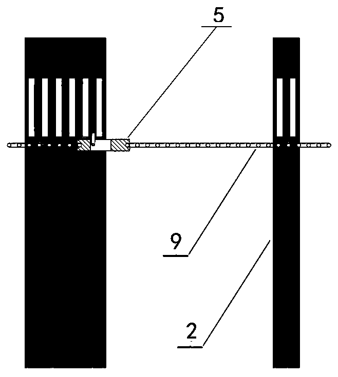
[0032] Figure 1-Figure 5 The traditional method of pulling the plate of the filter press uses a set of pulling plate mechanism. Driven by the motor, the plate is repeatedly taken and pulled to complete the work of removing the filter cake from the pulling plate of the entire filter press.

[0033] Figure 6-Figure 7 This is a schematic diagram of the three filter plates of the present invention as a group of drawing plates connected by connecting wires. The working process is that each time the drawing mechanism pulls the first filter plate of a group of filter plates, the first filter plate is Pull open each filter plate in this group in turn by pulling the string to make the filter cake in each filter plate of this group fall off. When the first filter plate of this group is close to the last filter plate of the previous group, push the previous group of filter plates to close, so that the previous group of filter plates are closed sequentially from the last one. When the previ...


PUM


Abstract

The invention relates to a continuous plate pulling system of a filter press in the field of sludge treatment industrial equipment manufacture.The continuous plate pulling system comprises a thrust plate, a pressing plate and a control system, wherein the thrust plate and the pressing plate are arranged in pairs in a matched mode, and several filter plates are arranged between the thrust plate and the pressing plate.Plate pulling mechanisms composed of plate pulling hooks, chains, driving motors, redirection pressing plates and return baffles are arranged at the front-back horizontal positions of the outer portions of the thrust plate, the filter plates and the pressing plate.The number of the filter plates is from 10 to 120.The filter plates are connected through connecting lines.The plates are pulled continuously, filter cakes are unloaded continuously, the plate pulling time is shortened, efficiency is improved in a multiplied mode, there is enough time for each filter plate to unload the filter cakes, and the problem that the filter cakes are scattered on the ground and pollute the environment is solved; the two plate pulling mechanisms are adopted for cooperative operation, and therefore the problems that when the plate pulling hooks pass by the filter plates which are closed, the former closed filter plate may be pulled, consequently, the plate pulling effect is affected, and work efficiency is lowered are solved.The continuous plate pulling system is simple in structure, convenient to maintain and easy to use and popularize.

Description

Technical field [0001] The invention relates to the manufacturing field of industrial equipment for papermaking, brewing and sludge treatment, and specifically refers to a continuous drawing plate system of a filter press used in a plate and frame filter press, a chamber filter press and a diaphragm filter press. Background technique [0002] In traditional papermaking, brewing, sludge treatment and other related industries, materials with high water content are dehydrated, and most of them use solid-liquid separation methods, mainly using centrifugal dehydrators, belt filter presses, plate and frame filter presses, and vacuum Filtering equipment such as filter presses filter solids out of the liquid to achieve the purpose of solid-liquid separation. [0003] At present, the existing filter presses are mainly ordinary filter presses and automatic pull plate filter presses. After each press filter is completed, the ordinary filter presses need to manually remove a large number of he...

Claims


Application Information

Patent Timeline
Patent Type & Authority Patents(China)
IPC IPC(8): B01D25/172
CPCB01D25/172
Inventor 王军
Owner 王军
Why Eureka
Try Eureka