Equipment for Solder Fume Purification

A technology for flue gas purification and equipment, which is applied in the direction of gas treatment, use of liquid separation agents, chemical instruments and methods, etc. It can solve the problems of poor air permeability of filter sheets, limited adsorption capacity, discounted adsorption effect, etc., and achieves small airflow resistance and high absorption Strong ability and high purification effect

Active Publication Date: 2017-10-03
南通中奥车用新材料有限公司
View PDF4 Cites 1 Cited by
  • Summary
  • Abstract
  • Description
  • Claims
  • Application Information

AI Technical Summary

Problems solved by technology

[0002] The smoke generated by the solder wire during welding is due to the gasification of the flux in the solder wire when it meets the high-temperature electric soldering iron. These suspended smoke and odorous gases not only directly affect the health of the staff, but also seriously affect the air quality. , destroying the ecological environment, and at present, the mechanical equipment used in the treatment of solder fume is relatively lacking, or the work performance is relatively simple, generally the principle of directly using the fan to absorb the solder fume through the filter, this is not only because The limited adsorption capacity of the filter makes it troublesome to replace the filter frequently, and because the air permeability of the filter is poor, the filter that is too thick will seriously affect the purification efficiency of the equipment, and the filter that is too thin will greatly reduce the adsorption effect, and At present, this type of equipment cannot maintain high purification efficiency and miniaturized equipment for home amateurs. Therefore, a miniaturized, high purification efficiency, easy maintenance, easy to use, environmentally friendly, and energy-saving equipment for soldering fume is designed. Purification equipment has become an urgent problem to be solved in industrial production and sustainable development

Method used


Image

  • Equipment for Solder Fume Purification
  • Equipment for Solder Fume Purification
  • Equipment for Solder Fume Purification

Examples


Embodiment

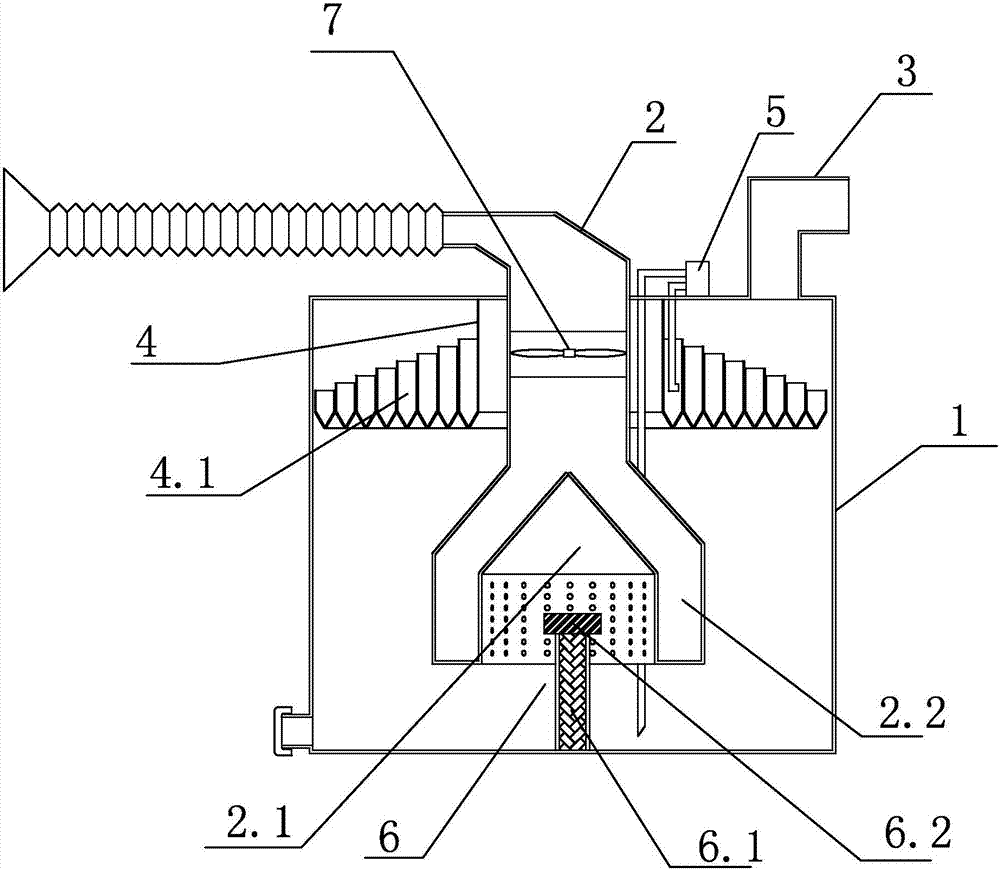
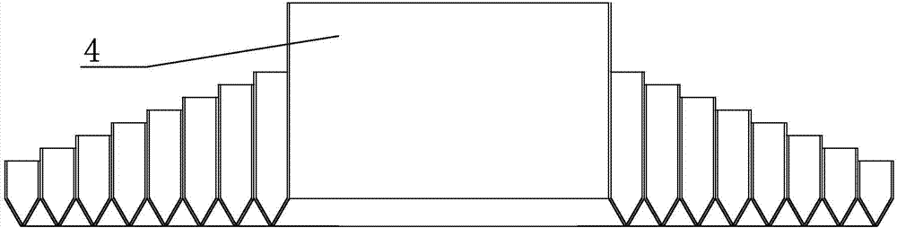
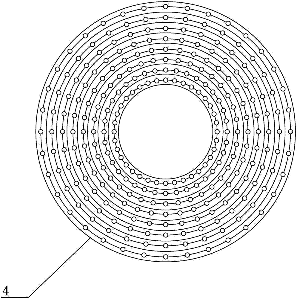
[0021] Such as Figure 1-4 As shown, a device for purifying solder fume includes a purification box 1, an air intake pipe 2 extending through the top plate of the purification box 1 into its interior, and an exhaust pipe 3 communicating with the purification box 1; The outer wall of the air inlet pipe 2 is sealed and connected with the top plate of the purification box 1; the end surface of the outlet end of the air inlet pipe 2 is concaved into a cavity 2.1, and the outer wall of the air inlet pipe 2 surrounds the cavity of the concave cavity 2.1 The wall forms a cavity 2.2; the cavity wall of the concave cavity 2.1 is provided with a number of exhaust holes; the top plate of the purification box 1 is provided with a liquid distributor 4 and is used to pump the liquid at the bottom of the purification box 1 into The water pump 5 of the liquid distributor 4; the bottom of the liquid distributor 4 is provided with a number of drain holes distributed along the circumference of t...


PUM


Abstract

The invention discloses a device used for tin soldering flue gas purification. The device comprises a purification box (1), a gas inlet pipe (2) penetrating through a top plate of the purification box (1)to extend into the purification box (1), and at least one gas outlet pipe (3) communicated with the purification box (1), wherein the outer wall of the gas inlet pipe (2) is hermetically connected with the top plate of the purification box (1); the end surface of the gas outlet end of the gas outlet pipe (2) is inwards recessed to form a recessed cavity (2.1); the outer wall of the gas inlet pipe (2) surrounds the cavity wall of the recessed cavity (2.1) to form a cavity (2.2); and a plurality of gas outlets are formed in the cavity wall of the recessed cavity (2.1). The device has the advantages that the device can be miniaturized, the purification efficiency is high, the device is maintained conveniently, the use is simple, and the device is environment-friendly and energy-saving.

Description

technical field [0001] The invention relates to the technical field of environmental protection purification equipment, in particular to equipment for purifying solder fume. Background technique [0002] The smoke generated by the solder wire during welding is due to the gasification of the flux in the solder wire when it meets the high-temperature electric soldering iron. These suspended smoke and odorous gases not only directly affect the health of the staff, but also seriously affect the air quality. , destroying the ecological environment, and at present, the mechanical equipment used in the treatment of solder fume is relatively lacking, or the work performance is relatively simple, generally the principle of directly using the fan to absorb the solder fume through the filter, this is not only because The limited adsorption capacity of the filter makes it troublesome to replace the filter frequently, and because the air permeability of the filter is poor, the filter tha...

Claims


Application Information

Patent Timeline
Patent Type & Authority Patents(China)
IPC IPC(8): B01D47/00B01D47/06B01D47/02B01D53/18
CPCB01D47/00B01D47/024B01D47/06B01D53/18B01D2252/103B01D2258/0283
Inventor 顾飞华李丹
Owner 南通中奥车用新材料有限公司
Why Eureka
Try Eureka