Hand-held high-frequency vibration cleaner for implantable medical devices
A medical device and high-frequency vibration technology, applied in the field of medical devices, can solve the problems of reducing the safety factor of cleaning time, patient injury during valve cleaning time, and lowering blood pressure of patients, so as to achieve good cleaning effect, reduce the risk of stroke, and reduce the risk of stroke. Effect of cleaning time
- Summary
- Abstract
- Description
- Claims
- Application Information
AI Technical Summary
Problems solved by technology
Method used
Image
Examples
Embodiment 1
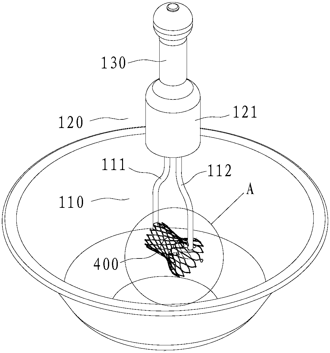
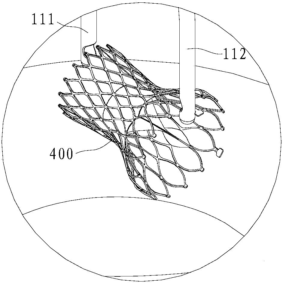
[0061] Such as figure 1 As shown, the handheld high-frequency vibration cleaner provided in this embodiment includes, from bottom to top, a holding component 110 , a vibration generating source 120 and a handle 130 .
[0062] The vibration generating source 120 is provided with a housing 121 outside, which is generally cylindrical in shape. The top surface of the housing 121 is fixedly connected to the handle 130 , and the bottom surface of the housing 121 is provided with an escape opening for avoiding the retaining part 110 .
[0063] The shell 121 is provided with a voice coil motor and a matching driving circuit. The voice coil motor includes a coil and a magnet that cooperate with each other. The vibration frequency of the coil is 100-1000 Hz. A frequency adjustment switch is provided in the drive circuit, and the frequency adjustment switch button is set on the casing 121 (not shown in the figure), and the vibration frequency of the coil can be continuously adjusted thro...
Embodiment 2
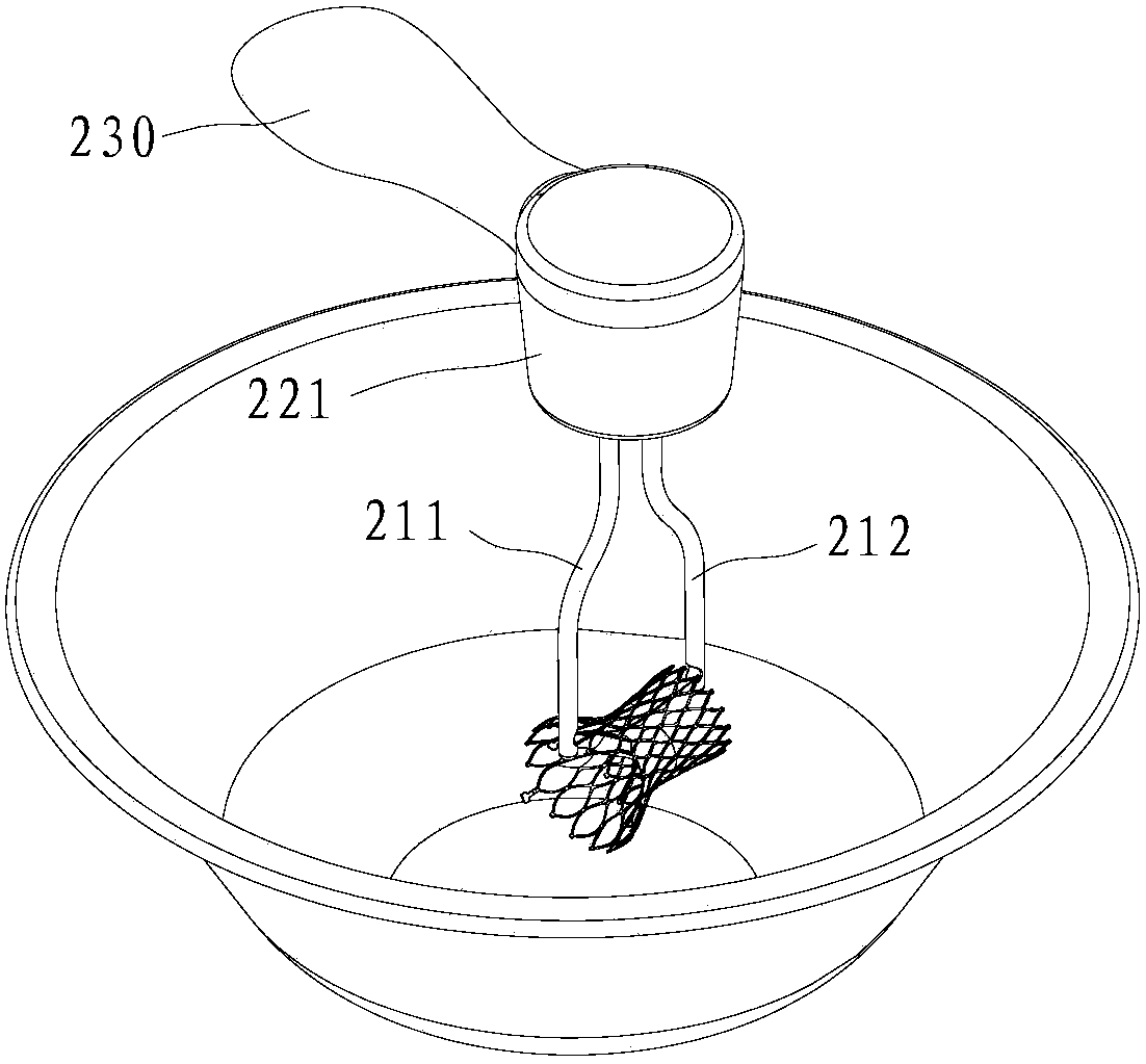
[0077] The only difference between this embodiment and Embodiment 1 is that the angle between the extension direction of the handle 230 and the extension direction of the clamping arm is 90 degrees.
[0078] Such as image 3 As shown, the housing 221 is generally cylindrical, the clamping arm 211 and the clamping arm 212 are arranged at the bottom of the housing 221, and the whole extends along the vertical direction in the figure, the handle 230 is fixed on the side wall of the housing 221, and extends along the horizontal direction. direction extension.
Embodiment 3
[0080] The only difference between this embodiment and Embodiment 1 is that the structure of the part where the end of the clamping arm cooperates with the instrument to be cleaned is different.
[0081] In this embodiment, the end of the clamping arm is a bifurcated structure, and the fork of the bifurcated structure forms a card slot, and the opening direction of the card slot is upward. When clamping the instrument to be cleaned, the instrument to be cleaned can be hung on the card slot to avoid During cleaning, disengage the clamping arms.
PUM
 Abstract
Description
Claims
Application Information
 - R&D
- Intellectual Property
- Life Sciences
- Materials
- Tech Scout
- Unparalleled Data Quality
- Higher Quality Content
- 60% Fewer Hallucinations
Browse by: Latest US Patents, China's latest patents, Technical Efficacy Thesaurus, Application Domain, Technology Topic, Popular Technical Reports.
© 2025 PatSnap. All rights reserved.Legal|Privacy policy|Modern Slavery Act Transparency Statement|Sitemap|About US| Contact US: help@patsnap.com


