Rotary tool for welding

A tooling and articulation technology, applied in welding equipment, auxiliary welding equipment, welding/cutting auxiliary equipment, etc., can solve the problems of high labor intensity and low welding efficiency, and achieve the effect of reducing labor intensity and improving welding efficiency.

Inactive Publication Date: 2016-07-13
天津右岸牵伊网络科技有限公司
View PDF0 Cites 3 Cited by
  • Summary
  • Abstract
  • Description
  • Claims
  • Application Information

AI Technical Summary

Problems solved by technology

[0003] The problem to be solved by the invention is that in the manual welding process, the size of the larger welded parts exceeds the welding range that the welding torch can reach. After a part of the welding is completed, the welded parts need to be adjusted with the help of lifting tools to improve the welding efficiency. low, labor intensive

Method used


Image

  • Rotary tool for welding
  • Rotary tool for welding
  • Rotary tool for welding

Examples


Embodiment Construction

[0020] Now in conjunction with accompanying drawing, this welding overturning frock is described in further detail.

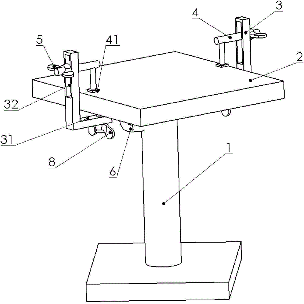
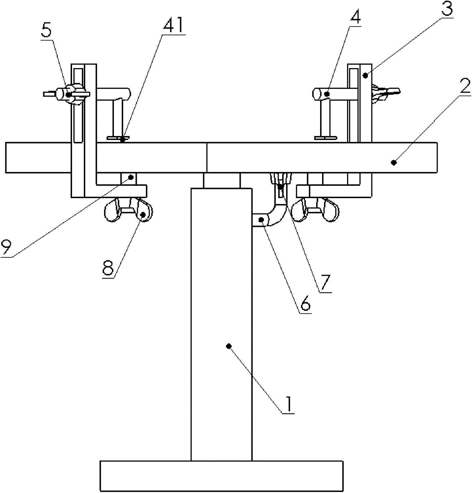
[0021] As shown in 1, 2, and 3, a rotary tooling for welding, including a support 1, an operating table 2, and a plurality of pressing units;

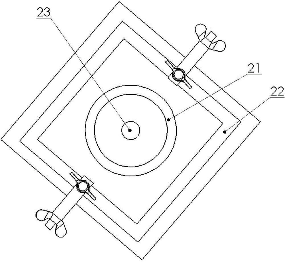
[0022] The middle part of the bottom surface of the console 2 is provided with a positioning groove 23, and the positioning groove 23 is hinged with the upper part of the support 1;

[0023] A positioning unit is provided at the hinged position between the console 2 and the support 1;

[0024] The plurality of pressing units are respectively slidingly connected to the operating platform 2 .

[0025] Such as figure 2 As shown, the positioning unit includes a positioning shaft 6, a positioning groove 21, and a second clamping element 7. The positioning shaft 6 is an inverted "L" shape, and its lower part is fixedly connected to the support 1. The positioning The groove 21 is located at the outer edge of the hinged pos...


PUM


Abstract

The invention provides a rotary tool for welding. The rotary tool for welding comprises a support, an operation table and a plurality of compressing units, wherein a positioning groove is formed in the middle part of the bottom of the operation table; the positioning groove is hinged to the upper part of the support; a positioning unit is arranged at a hinge position between the operation table and the support; the plurality of compressing units are connected to the operation table in a sliding way respectively. By adopting the rotary tool for welding, the labor intensity and labor force during welding of large-sized welded parts can be lowered greatly, and the welding efficiency is increased.

Description

technical field [0001] The invention relates to the field of welding, in particular to a rotary tool for welding Background technique [0002] In the process of manual welding, it is often encountered that the size of the larger welded parts exceeds the welding range that the welding torch can reach. After a part of the welding is completed, it is necessary to adjust the welded parts with the help of lifting tools so that the unwelded parts are in the welding torch Within the range that can be achieved, the time required for welding is prolonged, the welding efficiency is reduced, the consumption of working hours is increased, and the labor intensity is high, which in turn affects the delivery time of the product where the welded part is located. Contents of the invention [0003] The problem to be solved by the invention is that in the manual welding process, the size of the larger welded parts exceeds the welding range that the welding torch can reach. After a part of th...

Claims


Application Information

Patent Timeline
Patent Type & Authority Applications(China)
IPC IPC(8): B23K37/04B23K37/047
Inventor 谢万库
Owner 天津右岸牵伊网络科技有限公司
Why Eureka
Try Eureka