
Simple and efficient conveying and cutting device

A cutting device and high-efficiency technology, which is applied in the direction of sawing machine, metal sawing equipment, metal processing, etc., can solve the problems of difficult operation, high labor cost, time-consuming and laborious, etc., and achieve saving of manufacturing cost, high work efficiency and flexible application Effect

Active Publication Date: 2016-07-13
MEICHENG NEW MATERIAL TECH JIANGSU CO LTD
View PDF7 Cites 5 Cited by
  • Summary
  • Abstract
  • Description
  • Claims
  • Application Information

AI Technical Summary

Problems solved by technology

However, this process is usually cut with a manual manual cutting machine. This method of cutting is generally low in efficiency, labor-intensive, high in labor costs, time-consuming and labor-intensive, and there are differences in product quality and high rework rate; cutting length and port verticality and other changes, unable to meet the ever-increasing product quality requirements
In addition, during the cutting process, the operator needs to manually operate the cutting equipment, and a large amount of dust will be generated during the cutting process, which will have a great impact on the personal safety and labor protection of the workers. Only by equipped with protective masks, dust masks, etc. Simple protection cannot achieve effective human-machine isolation
However, some automatic cutting devices on the market have complex structures, high manufacturing costs, and are not easy to operate
In addition, the material needs to be tracked throughout the cutting process, which takes a long time to cut and the work efficiency is not high

Method used


Image

  • Simple and efficient conveying and cutting device
  • Simple and efficient conveying and cutting device
  • Simple and efficient conveying and cutting device

Examples


Embodiment Construction

[0021] The present invention will be further explained below in conjunction with the accompanying drawings and specific embodiments.

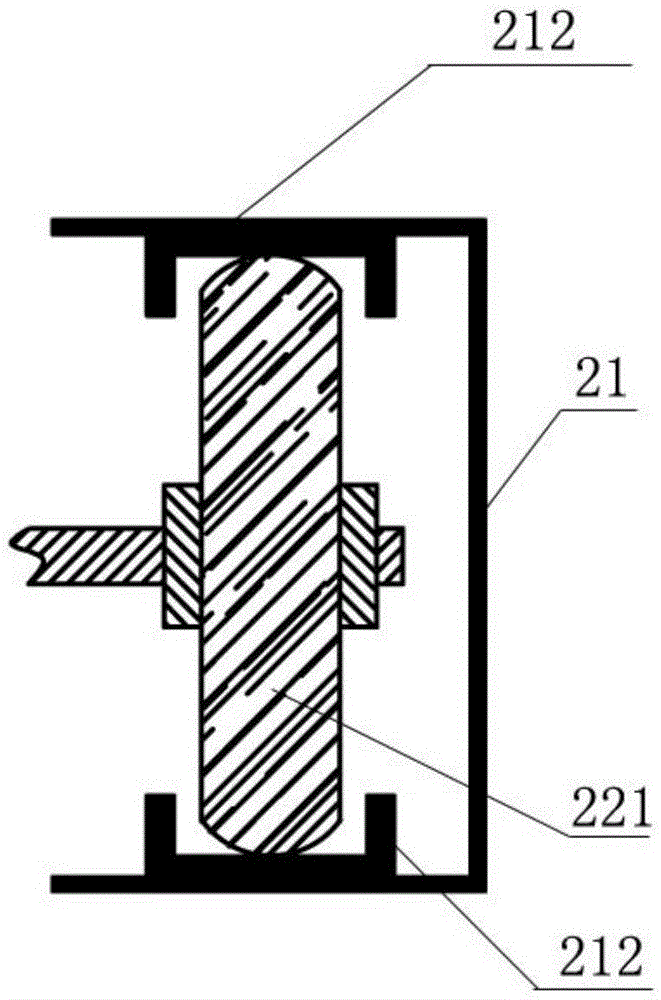
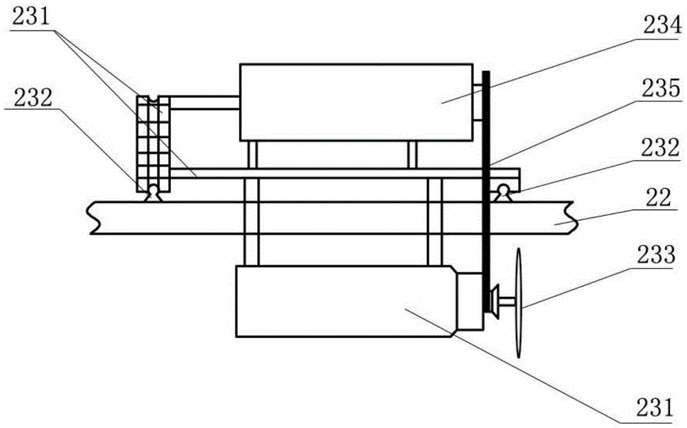
[0022] Such as Figure 1-5 The simple and efficient transportation and cutting device shown includes a transmission mechanism 1, a cutting mechanism 2, a transportation mechanism 3 and a servo motor 4, and the transmission mechanism 1 is arranged on one side of the cutting mechanism 2; connected, pass through the cutting mechanism 2 and extend to the other side of the cutting mechanism 2;

[0023] Wherein, the conveying mechanism 1 includes a group of product conveyor belts 11, a group of template conveyor belts 12, a conveyor frame 13 and a chain 14, the product conveyor belt 11 and the template conveyor belt 12 are arranged on the conveyor frame 13, and the product conveyor belt 11 is located above the template conveyor belt 12; the product conveyor belt 11 and the template conveyor belt 12 are provided with a set of conveying rollers, and t...


PUM


Abstract

The invention discloses a simple and efficient conveying and cutting device.The simple and efficient conveying and cutting device comprises a conveying mechanism, a cutting mechanism, a transporting mechanism and a servo motor, wherein the conveying mechanism is arranged on one side of the cutting mechanism, the transporting mechanism is connected with the conveying mechanism, penetrates through the cutting mechanism and extends to the other side of the cutting mechanism, and the servo motor is arranged at the connecting portion of the conveying mechanism and the transporting mechanism.The simple and efficient conveying and cutting device is simple in structure, reasonable in design and easy to produce; synchronous working of two mechanisms can be controlled through one servo motor, so that working efficiency is high, manufacturing cost is reduced, and the simple and efficient conveying and cutting device is suitable for large-scale industrial application.

Description

technical field [0001] The invention belongs to the electromechanical field, and in particular relates to a simple and efficient transport cutting device for various products such as plates and metals. Background technique [0002] A variety of products, including plates, plastics, steel plates, aluminum plates, etc., often need to be cut before packaging and other follow-up processing after production. However, this process is usually cut with a manual manual cutting machine. This method of cutting is generally low in efficiency, labor-intensive, high in labor costs, time-consuming and labor-intensive, and there are differences in product quality and high rework rate; cutting length, port verticality And other changes, unable to meet the increasing product quality requirements. In addition, during the cutting process, the operator needs to manually operate the cutting equipment, and a large amount of dust will be generated during the cutting process, which will have a grea...

Claims


Application Information

Patent Timeline
IPC IPC(8): B26D1/60B26D5/08B26D7/26B26D7/06B26D7/01B23D45/20
CPCB23D45/20B26D1/60B26D5/08B26D7/01B26D7/0625B26D7/2621
Inventor 叶友春
Owner MEICHENG NEW MATERIAL TECH JIANGSU CO LTD
Learn More