Drag reduction and efficiency enhancement ship

A ship and hull technology, applied in the direction of ship propulsion, hull, ship parts, etc., can solve the problems of not reaching the reverse rotation output power of the main engine propeller, affecting the reverse speed of the ship, affecting the power efficiency of the ship, etc., and achieving flexible and convenient steering , outstanding effect, fast effect

Active Publication Date: 2017-11-03
王军辉
View PDF4 Cites 0 Cited by
  • Summary
  • Abstract
  • Description
  • Claims
  • Application Information

AI Technical Summary

Problems solved by technology

Because of the existence of the backward drag force, it will inevitably limit the sailing speed of the ship to a certain extent and affect the power efficiency of the ship.
The conventional structure of the stern of existing ships and warships will also form a relatively large stern resistance facade when the ship is in reverse, and the area of ​​water flow resistance encountered by the ship in reverse will affect the reverse speed of the ship
In addition, when the main engine propeller is reversed, most of the jet flow will act on the hull elevation at the tail of the hull, offsetting most of the jet flow force, and only part of the jet flow will rush to the surroundings of the hull tail to make the ship reverse. Therefore, the speed of the ship is slow when going backwards, which is far from the effect of the reverse rotation output power of the propeller of the main engine
Existing ordinary ships and warships all have a single rudder structure. Due to the limited stress area of ​​a single rudder itself, the turning radius of the ship will be relatively large when turning, which hinders the efficiency of the ship. All of the above are existing Weaknesses in ship technology

Method used


Image

  • Drag reduction and efficiency enhancement ship
  • Drag reduction and efficiency enhancement ship
  • Drag reduction and efficiency enhancement ship

Examples


Embodiment 1

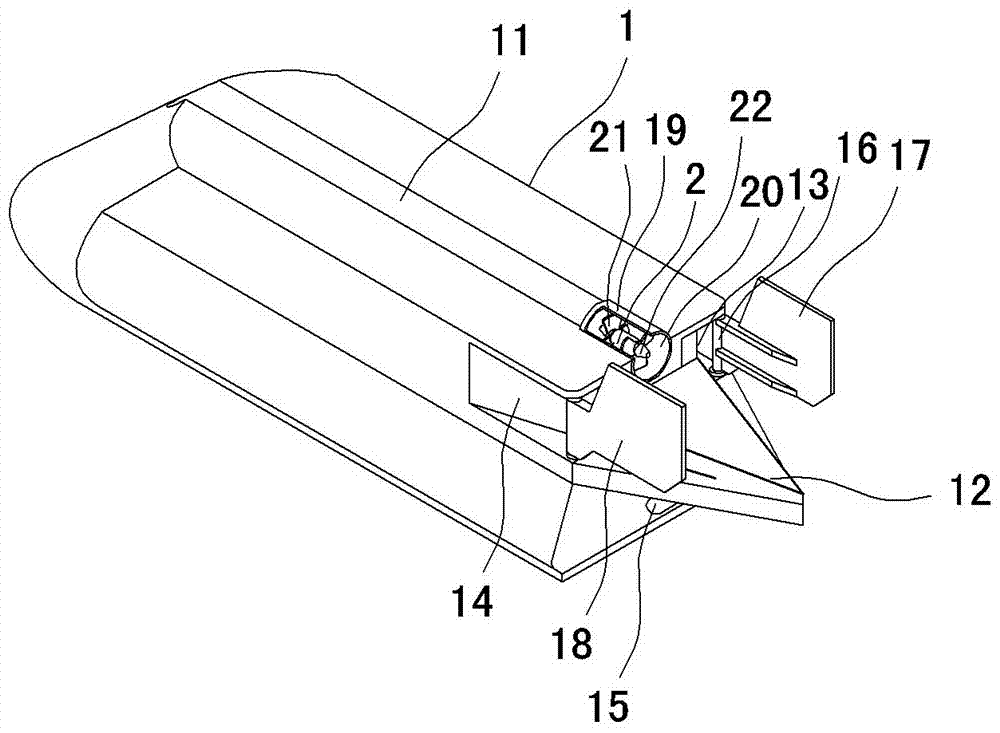
[0010] Embodiment one, such as figure 1 , figure 2 As shown, it includes a hull 1 and a propeller 2. The bottom of the hull 1 is forwardly provided with a diversion groove 11 recessed into the hull 1 and opening to the bottom and rear of the hull 1 from the rear of the hull 1. The rear portion stretches to the front of the hull 1 and opens to the front of the hull 1 or only stretches to a certain distance ahead of the rear of the hull 1. The propeller 2 is positioned in the diversion groove 11 and is installed on the hull 1. There is a vortex eliminator 12, the front side of the vortex eliminator 12 is connected to the upper and lower sides of the hull 1, and the lower side is located above the bottom of the diversion groove 11 and submerged below the water level line. The depth gradually deepens towards the left oblique water tank 13 that opens to the left and rear sides of the hull 1, and the stern of the hull 1 is located on the underwater right side wall. Right obliquel...

Embodiment 2

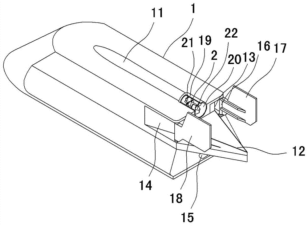
[0016] Embodiment two, such as image 3 , Figure 4 As shown, the difference from the first embodiment is that the propeller 2 is only provided with a rear propeller 22 towards the rear of the hull 1 .

[0017] Technical effect of the present invention:

[0018] 1. Since the ship is equipped with a vortex breaker 12 with a wide front and a sharp rear, the water flow can flow down when the ship sails forward, and no vortex phenomenon can be formed at the tail of the hull, which means that the ship cuts off the existing ship tail. Part of the eddy current is equivalent to cutting off part of the eddy current resistance when sailing forward, thereby improving the efficiency of the ship when sailing forward.

[0019] 2. When the ship is sailing forward, since the left and right oblique water tanks 13 and 14 are respectively provided on both sides of the stern of the hull, the two parallel water tanks can reduce the cross-sectional area of ​​the hull stern, which is equivalent to...


PUM


Abstract

The invention relates to a resistance reduction and efficiency improvement ship which comprises a ship body (1) and a propeller (2), the bottom of the ship body (1) is provided with a diversion trench (11), the propeller (2) is located in the diversion trench (11) and mounted in the ship body (1), the rear portion of the ship body (1) is provided with an eddy dissipation device (12), the left side wall, located under water, of the tail of the ship body (1) is provided with a left inclined downstream groove (13), and the right side wall, located under water, of the tail of the ship body (1) is provided with right inclined downstream groove (14).When the ship sails forward, eddy formed at the tail of the ship body is smaller, backward dragging force to the ship body is smaller, the forward sailing speed can be raised, power efficiency can be improved, the speed of the ship which sails backwards can be higher, efficiency is higher, and steering is more flexible and convenient; compared with a warship of the same level, the sailing speed increase, the sailing speed, the steering speed and the backward sailing speed are further increased compared with an ordinary ship and warship under the situation that the output power is consistent, the advantages are more obvious, and the effect is more outstanding.

Description

technical field [0001] The invention relates to ships, in particular to a ship that can reduce traveling resistance and increase efficiency. Background technique [0002] The underwater parts of the tail of existing ships and warships are basically vertical structures, and the propellers of the main engine are all protruding from the rear of the tail of the hull. This structure will cause the ship to sail forward. There will be a steady stream of vortices at the tail. Due to the continuous emergence of this vortex, there will be a continuous backward drag force on the ship, and the faster the propeller of the main engine rotates, the faster the speed of the vortex will be. The greater the force. Just because of the existence of the backward drag force, the sailing speed of the ship must be limited to a certain extent, which affects the power efficiency of the ship. The conventional structure of the stern of existing ships and warships will also form a considerable stern re...

Claims


Application Information

Patent Timeline
Patent Type & Authority Patents(China)
IPC IPC(8): B63B1/32B63H5/16B63H25/38
CPCB63B1/32B63H5/16B63H25/38Y02T70/10
Inventor 王军辉
Owner 王军辉
Why Eureka
Try Eureka