Steel body PDC (Polycrystalline Diamond Compact) directional bit for directional drilling under coal mine

A technology of directional drilling and directional drill bits, which is applied in the direction of drill bits, earthwork drilling, drilling equipment, etc. It can solve the problems of high cutting resistance, PDC cutter positioning accuracy needs to be improved, and high production cost, and achieves strong branching ability and realizes Effects of repeated use and low production cost

Inactive Publication Date: 2016-07-13
SHAANXI TAIHE TECH CO LTD
View PDF7 Cites 4 Cited by
  • Summary
  • Abstract
  • Description
  • Claims
  • Application Information

AI Technical Summary

Problems solved by technology

Most of the currently used directional drills are flat-bottomed matrix-type PDC drills. The disadvantages are that the distribution of PDC cutters is unreasonable, the cutting resistance is large, and limited by manufacturing technology, the positioning accuracy of PDC cutters needs to be improved, and the process is complicated. Production higher cost

Method used


Image

  • Steel body PDC (Polycrystalline Diamond Compact) directional bit for directional drilling under coal mine

Examples


specific Embodiment 1

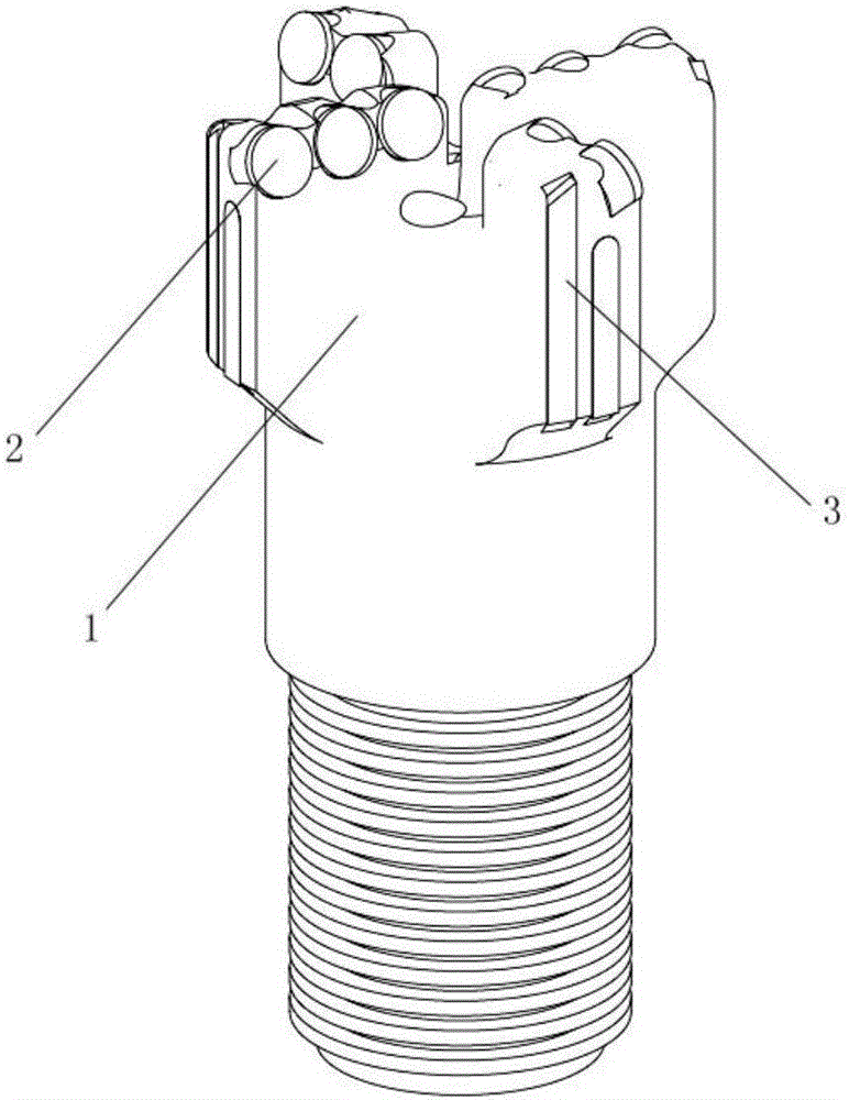
[0022] Such as figure 1 As shown, a steel body type PDC directional drill bit for directional drilling in underground coal mines includes a drill bit steel body 1, four blades and diamond-impregnated gage blocks 3,

[0023] The outer surface of one end of the drill bit steel body 1 is provided with threads,

[0024] The bottom surface of the other end of the drill bit steel body 1 is welded with four blades, and the outermost side of the blades is welded with PDC cutting teeth 2, and the PDC cutting teeth 2 are distributed in a scraper pattern.

[0025] The outer wall of the other end of the drill steel body 1 is evenly welded with a plurality of diamond-impregnated gauge blocks 3 , and the multiple diamond-impregnated gauge blocks 3 form a gauge surface, which is perpendicular to the PDC cutting teeth 2 .

[0026] Further, the steel body 1 of the drill bit is made of alloy steel.

[0027] Further, the center distances of the outermost PDC cutting teeth 2 are equal.

[0028...

specific Embodiment 2

[0032] Roughly the same as specific embodiment 1, the difference only lies in:

[0033] A steel body type PDC directional drill bit for directional drilling in coal mines includes three blades;

[0034] The height of the outgoing edge of the PDC cutter 2 is 2mm;

[0035] The diamond concentration of the diamond-impregnated gauge block 3 is 120%.

specific Embodiment 3

[0036] Roughly the same as specific embodiment 1, the difference only lies in:

[0037] A steel body type PDC directional drill bit for directional drilling in coal mines includes six blades;

[0038] The height of the outgoing edge of the PDC cutter 2 is 1.5 mm;

[0039] The diamond concentration of the diamond-impregnated gauge block 3 is 90%.


PUM


Abstract

The invention relates to a steel body PDC (Polycrystalline Diamond Compact) directional bit for directional drilling under a coal mine. The steel body PDC directional bit comprises a bit steel body, at least three blade edges and impregnated diamond gauge protection blocks, wherein the outer side face of one end of the bit steel body is provided with a thread; a plurality of blade edges are welded on the bottom surface of the other end of the bit steel body; PDC cutting teeth are welded on the outermost sides of the blade edges; the PDC cutting teeth are distributed in a scraper form; a plurality impregnated diamond gauge protection blocks are uniformly welded on the outer side wall of the other end of the bit steel body; the plurality of impregnated diamond gauge protection blocks form a gauge protection surface; the gauge protection surface is vertical to the PDC cutting teeth. The steel body PDC directional bit for directional drilling under the coal mine disclosed by the invention has the beneficial effects that 1, the steel body PDC directional bit has high branch expanding capability and good gauge protection effect, and can replace a flat-bottom tire-body PDC directional bit; 2, the steel body PDC directional bit has high production efficiency and low production cost, can be subjected to secondary repair, and can be used repeatedly.

Description

technical field [0001] The invention belongs to the field of underground drilling in coal mines, in particular to a steel body type PDC directional drill bit for directional drilling in underground coal mines. Background technique [0002] Gas drainage and water control construction play an important role in coal mine safety production, and directional drilling technology has been widely used in recent years because of its advantages in controlling the drilling trajectory. [0003] However, in the construction of directional drilling, a PDC directional drill bit with excellent deflection performance can be used to achieve efficient directional drilling. Most of the currently used directional drills are flat-bottomed matrix-type PDC drills. The disadvantages are that the distribution of PDC cutters is unreasonable, the cutting resistance is large, and limited by manufacturing technology, the positioning accuracy of PDC cutters needs to be improved, and the process is complica...

Claims


Application Information

Patent Timeline
Patent Type & Authority Applications(China)
IPC IPC(8): E21B10/43E21B10/54C22C29/08
CPCE21B10/43C22C29/08E21B10/54
Inventor 彭腊梅刘伟邓代传田小军杨英男
Owner SHAANXI TAIHE TECH CO LTD
Why Eureka
Try Eureka