A wet multi-disc pressure loss brake

A brake, wet technology, applied in the direction of the brake type, axial brake, brake parts, etc., can solve the problems of spring preload elastic force can not be adjusted, static friction plate and brake shell stuck, machining requirements are relatively high, etc., to achieve Reduce the difficulty of machining, simplify the hydraulic system, and reduce the volume

Inactive Publication Date: 2017-05-17
XIAN UNIV OF SCI & TECH
View PDF3 Cites 0 Cited by
  • Summary
  • Abstract
  • Description
  • Claims
  • Application Information

AI Technical Summary

Problems solved by technology

Ordinary wet multi-disc brakes are prone to accidents due to brake failure when the engine fails or the pipeline bursts, and a second braking system is often required; multi-functional wet multi-disc brakes have good braking performance, but the braking system is relatively complicated and the cost is high
The spring preload of the traditional wet multi-disc pressure-loss brake cannot be adjusted, and the gap between the friction plates becomes larger after a period of use, which cannot be adjusted; when the engine fails or the pipeline bursts, the brake locks the wheel and cannot release the brake ;The outer ring of the static friction plate is a flower-toothed structure, which requires relatively high machining. It is easy to cause the static friction plate and the brake shell to be stuck when braking, and the flower-toothed static friction plate and the dynamic friction plate are installed together. After the cooling oil cavity is small, there will be poor heat dissipation

Method used


Image

  • A wet multi-disc pressure loss brake
  • A wet multi-disc pressure loss brake
  • A wet multi-disc pressure loss brake

Examples


Embodiment Construction

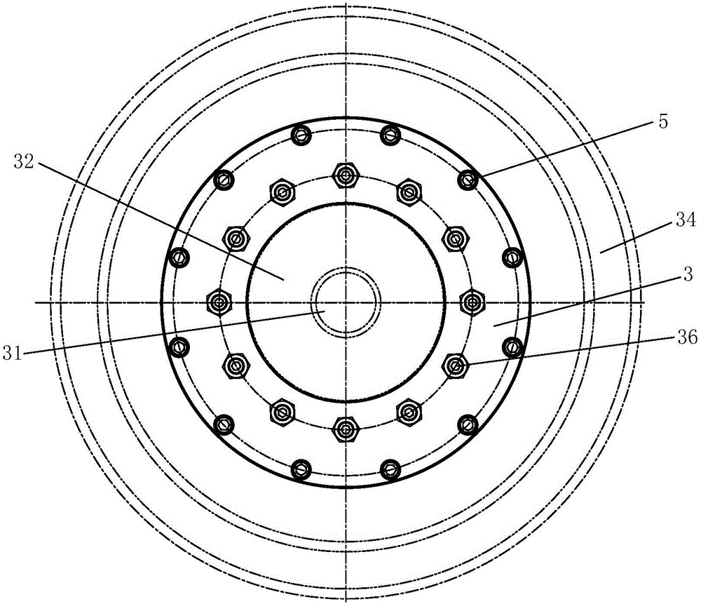
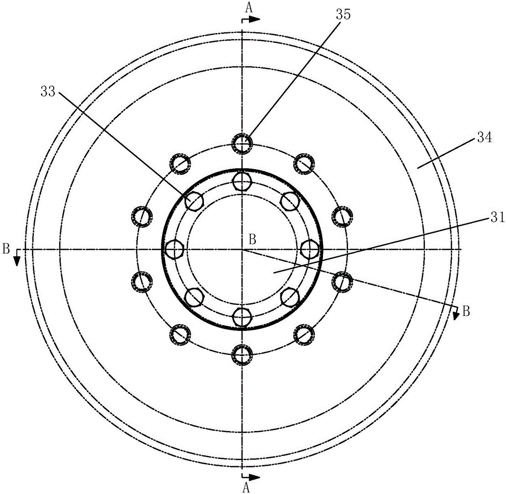
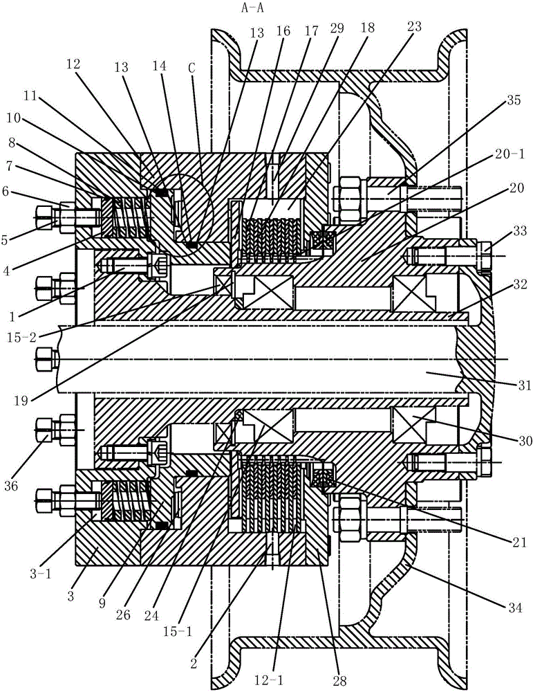
[0048] Such as figure 1 , figure 2 , image 3 and Figure 5 As shown, the present invention includes a fixed part and a rotating part, and the rotating part includes a spline shaft 20 and a rotating shaft 31, and the rotating shaft 31 passes through the spline shaft 20 and is fixedly connected with the spline shaft 20; the fixed part Including installation shell 3, brake shell 12, brake piston 9, baffle plate 28 and bearing sleeve 32, said brake shell 12 is arranged between installation shell 3 and baffle plate 28, said installation shell 3, brake shell 12 and the baffle plate 28 are fixed together, the brake piston 9 is set in the brake housing 12, a brake chamber 26 is formed between the brake housing 12 and the brake piston 9, and the brake housing 12 A hydraulic oil port 25 communicating with the brake chamber 26 is opened on the top, and a plurality of installation chambers 3-1 are evenly opened around the circumference of the installation shell 3, and a pair of brake...


PUM


Abstract

The invention discloses a wet multi-disc decompression brake which comprises a fixed part and a rotating part, wherein the rotating part comprises a splined shaft and a rotating shaft, and the rotating shaft penetrates through the splined shaft, and is fixedly connected with the splined shaft; the fixed part comprises a mounting casing, a brake casing, a brake piston, a retaining disc and a bearing sleeve, the brake casing is arranged between the mounting casing and the retaining disc, the mounting casing, the brake casing and the retaining disc are fixed together, the brake piston is arranged in the brake casing, and forms a brake cavity with the brake casing, a hydraulic oil port is formed in the brake casing, the mounting casing is circumferentially provided with a plurality of mounting cavities, elastic brake mechanisms are mounted on the mounting cavities, the bearing sleeve is connected with the splined shaft in a rotating manner, and is fixedly connected with the mounting casing, a cooling cavity is formed by the splined shaft, the brake piston, the brake casing and the retaining disc, a pressure disc, a kinetic friction plate and a static friction plate are arranged in the cooling cavity, and the splined shaft is sealed with the retaining disc. The wet multi-disc decompression brake is simple in structure, stable in working performance, long in service life and relatively low in cost, and does not need to be frequently maintained.

Description

technical field [0001] The invention belongs to the technical field of brakes, in particular to a wet multi-disc pressure loss brake. Background technique [0002] At present, in order to meet the special requirements of underground vehicles on the braking system, such as explosion-proof, waterproof, thermal stability, braking reliability, etc., the brakes mostly use wet multi-disc brakes with better braking performance in construction machinery. The wet multi-disc brake has stable working performance and does not require frequent maintenance. The service life is generally 3 to 5 times that of the dry brake, and the performance will not decline after more than two years of use. Wet multi-disc brakes are divided into ordinary wet multi-disc brakes, wet multi-disc loss-of-pressure brakes and multi-functional wet multi-disc brakes according to their functions and working principles. Ordinary wet multi-disc brakes are prone to accidents due to brake failure when the engine fail...

Claims


Application Information

Patent Timeline
Patent Type & Authority Patents(China)
IPC IPC(8): F16D55/46F16D69/00F16D65/84
CPCF16D55/46F16D65/84F16D69/00F16D2069/004
Inventor 张传伟苗旺
Owner XIAN UNIV OF SCI & TECH
Why Eureka
Try Eureka