Temperature measurement alarming device for electrical equipment jointing clamp

A technology for electrical equipment and alarm devices, applied in the field of alarm devices, can solve the problems of large connection gap between steel-cored aluminum stranded wires and equipment clamps, accelerated oxidation and scaling of contact surfaces, and poor operating conditions, and achieves simple structure, The installation is firm and reliable, and the effect of normal operation is guaranteed

Active Publication Date: 2016-07-13
STATE GRID SHANDONG ELECTRIC POWER +1
View PDF5 Cites 3 Cited by
  • Summary
  • Abstract
  • Description
  • Claims
  • Application Information

AI Technical Summary

Problems solved by technology

The connection between the bolt clamp and the wire has a small actual contact surface, which is greatly affected by the uniformity of the bolt crimping. This kind of clamp is usually placed outdoors, and the operating conditions are relatively harsh; at the same time, the ACSR and the equipment The connection gap of the cable clamp is relatively large. In areas with a lot of wind, frost, rain and snow, strong sunshine, and large temperature difference between day and night, it is greatly affected by the external environment. Coupled with the effect of electromagnetic fields, the oxidation and scaling of the contact surface are accelerated, resulting in Connector heat

Method used


Image

  • Temperature measurement alarming device for electrical equipment jointing clamp
  • Temperature measurement alarming device for electrical equipment jointing clamp
  • Temperature measurement alarming device for electrical equipment jointing clamp

Examples


Embodiment Construction

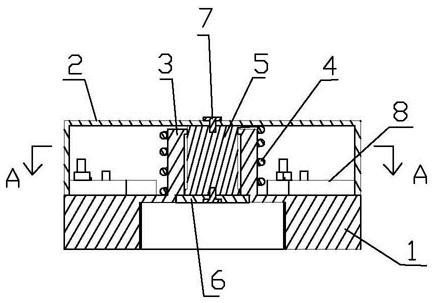
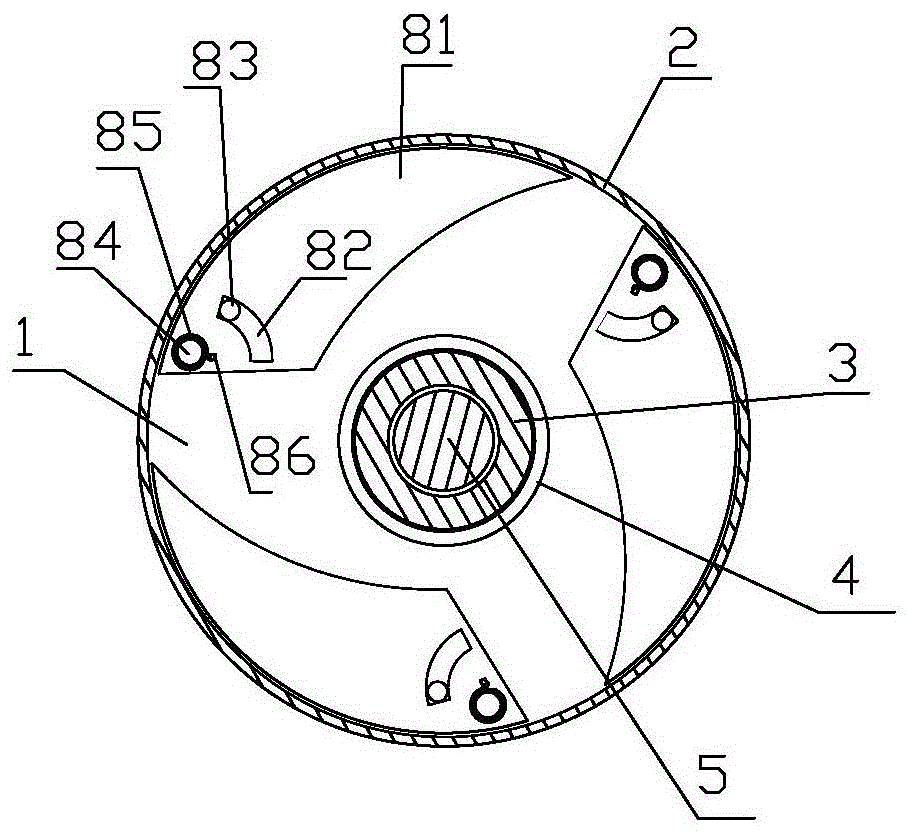
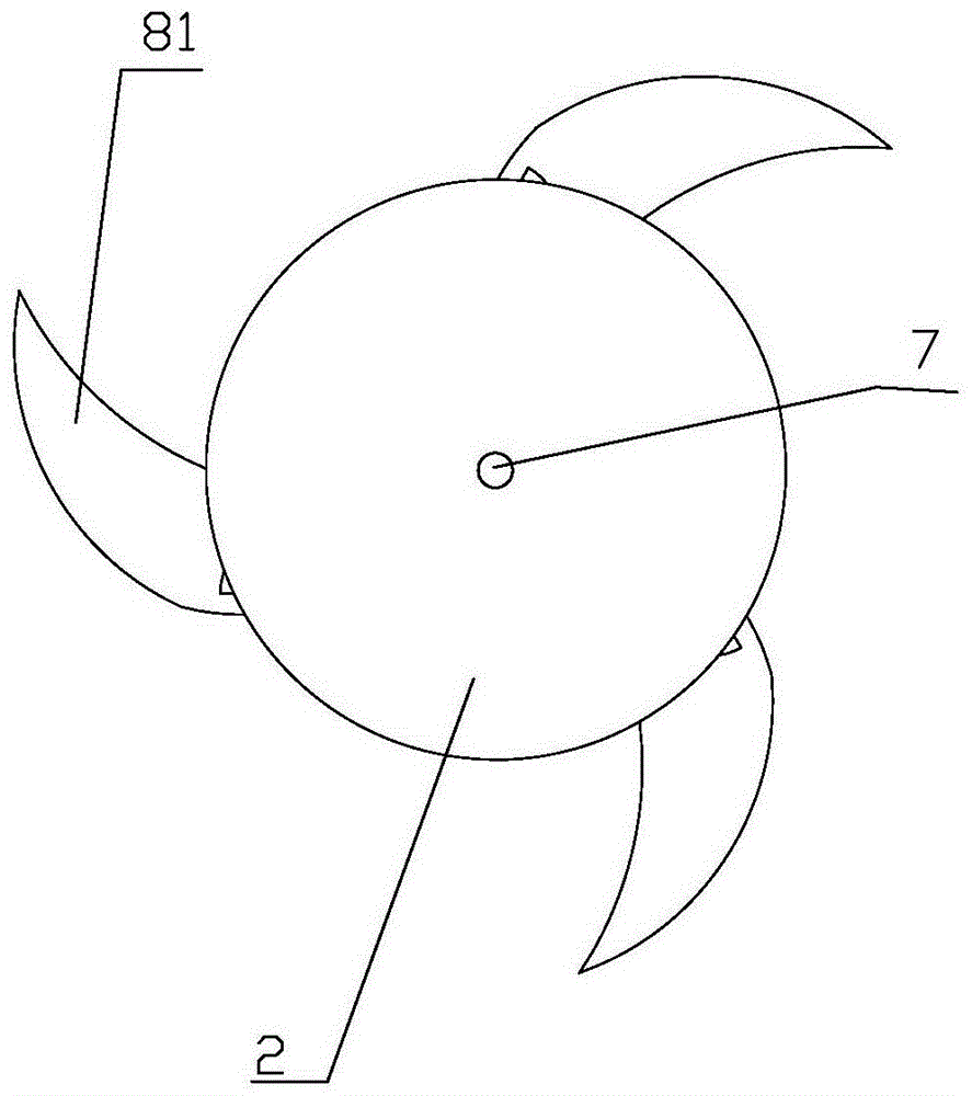
[0013] refer to figure 1 , figure 2 Make the invention. The temperature measurement and alarm device of the electrical equipment wiring clip includes a base 1 and an upper cover 2, the middle part of the base 1 is provided with a through hole, and the inner wall of the lower part of the through hole of the base 1 is provided with a screw thread suitable for the bolt, so that the base 1 is installed at the end of the bolt of the electrical equipment connection clamp, the upper cover 2 is set on the upper part of the base 1, and the lower end of the side wall of the upper cover 2 coincides with the upper plate surface of the base 1, and its feature is: the through hole of the base 1 The upper part is fixed with a sliding sleeve 3, and a sliding column 5 is arranged in the cavity of the sliding sleeve 3. The upper end of the sliding column 5 passes through the upper edge of the sliding sleeve 3 and is connected and fixed with the upper cover 2 through the screw 7. Between the u...


PUM

PropertyMeasurementUnit
melting pointaaaaaaaaaa

Abstract

The invention discloses a temperature measurement alarming device for an electrical equipment jointing clamp.The temperature measurement alarming device comprises a base and an upper cover, the middle of the base is provided with a through hole, the inner wall of the lower portion of the through hole formed in the base is provided with a thread matched with a bolt, the upper cover is arranged on the upper portion of the base in a covering mode, and the lower end edge of the side wall of the upper cover is matched with the upper plate face of the base.The temperature measurement alarming device is characterized in that the upper portion of the through hole formed in the base is fixedly provided with a sliding sleeve, a sliding column is arranged in a sliding sleeve cavity, the upper end of the sliding column penetrates out of the upper opening edge of the sliding sleeve to be fixedly connected with the upper cover through a screw, a spring arranged outside the sliding sleeve in a sleeving mode is arranged between the upper cover and the base, a fusible alloy gasket is fixedly connected with the lower end of the sliding column, the peripheral edge of the fusible alloy gasket is laid on the lower port edge of the sliding sleeve, and the upper plate face of the base is provided with a rotary warning device which is located in an upper cover cavity.The temperature measurement alarming device is simple in structure, convenient to use, small in size and firm and reliable in installation and is used by being installed to a bolt of the electrical equipment jointing clamp, and normal operation of equipment is guaranteed.

Description

technical field [0001] The invention relates to a warning device when the wiring clip of electrical equipment is heated, in particular to a temperature measuring and alarming device for the wiring clip of the electrical equipment, which is installed on the bolt of the wiring clip of the electrical equipment and used to judge whether the equipment joint is heated. Background technique [0002] Heating of the wiring clips of the electrical equipment in the substation is a common fault. When the wiring clips are seriously heated, the power should be cut off immediately, which seriously affects the reliability and safety of the electrical equipment operation, especially in summer and winter when the power load is large. , Electrical equipment wiring clips are more prone to heating faults. The terminal clamps currently used in electrical equipment are all provided with bolts for fastening, and the terminal clamps are fixedly connected to the wires firmly. The connection between ...

Claims


Application Information

Patent Timeline
Patent Type & Authority Applications(China)
IPC IPC(8): G01K1/02G01K1/14
CPCG01K1/02G01K1/14
Inventor 胡昌伦刘恒杰刘增昕亓晓燕谭延超张文栋吕刚丁吉峰刘振栋李新蕾郝振军王函旭侯秋华王涛王文君魏松广
Owner STATE GRID SHANDONG ELECTRIC POWER
Why Eureka
Try Eureka