TDI-CCD-based large-aperture long-focal length remote sensing camera distortion measurement device and measurement method

A remote sensing camera and measuring device technology, applied in the field of optical machinery, can solve problems such as the final image distortion correction residual, and achieve the effects of improving accuracy, saving money, and being easy to implement.

Active Publication Date: 2016-07-13
XI'AN INST OF OPTICS & FINE MECHANICS - CHINESE ACAD OF SCI
View PDF6 Cites 11 Cited by
  • Summary
  • Abstract
  • Description
  • Claims
  • Application Information

AI Technical Summary

Problems solved by technology

Due to the limited number of reference target settings, the accuracy of the obtained distortion coefficient will not be too high, which will cause a large residual error in the distortion correction of the final image

Method used


Image

  • TDI-CCD-based large-aperture long-focal length remote sensing camera distortion measurement device and measurement method
  • TDI-CCD-based large-aperture long-focal length remote sensing camera distortion measurement device and measurement method
  • TDI-CCD-based large-aperture long-focal length remote sensing camera distortion measurement device and measurement method

Examples


Embodiment Construction

[0028] The present invention will be described in detail below with reference to the drawings and specific embodiments.

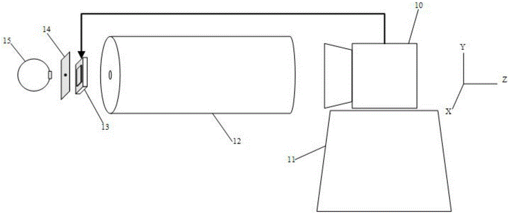
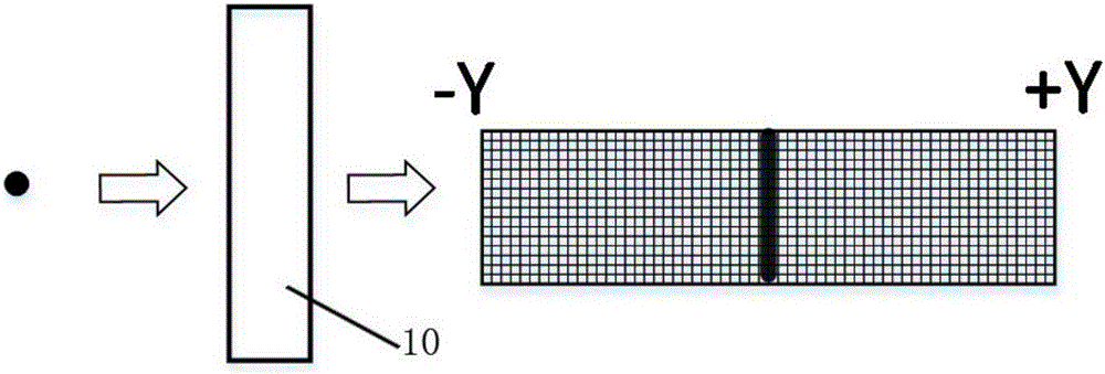
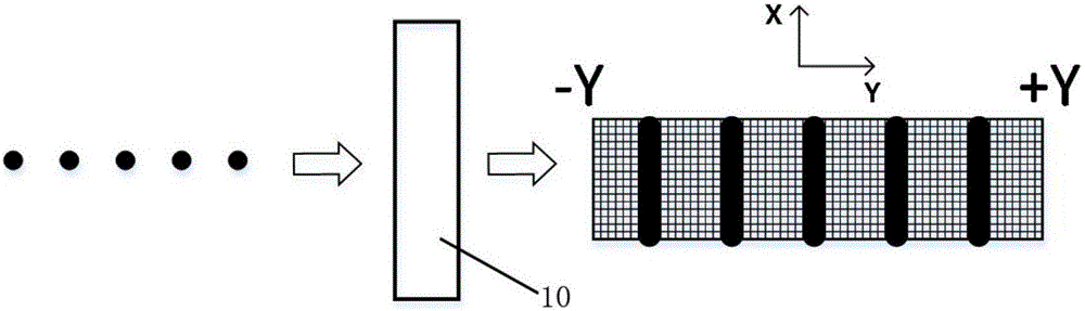
[0029] The camera based on the TDI-CCD large-aperture long focal length sensor is a type of line-scan camera. Its normal working mode is scanning, that is, there must be a certain relative movement between the camera and the imaged target during imaging, and the movement speed must be integrated with the imaging Match the time, otherwise there will be smear in the push sweep direction. When there is no relative movement between the imaged target and the camera, the imaging result is a vertical stripe parallel to the sweep direction, such as figure 2 .

[0030] When measuring the optical distortion of the camera in the normal working mode of the TDI-CCD large-aperture long-focus remote sensing camera, the parallel halo is used to simulate the target at infinity, and the star point target is maintained at a fixed position. Every time the two-dimensional turntable...


PUM


Abstract

The invention relates to a large-aperture long-focal length remote sensing camera distortion measurement device and a measurement method. The device comprises a collimator, a two-dimensional turntable, a mechanical shutter, an integrating sphere, a star point target, and a TDI-CCD long-focal length large-aperture remote sensing camera, wherein the TDI-CCD long-focal length large-aperture remote sensing camera is arranged on the two-dimensional turntable; the collimator is arranged at the entrance pupil place of the TDI-CCD long-focal length large-aperture remote sensing camera; and the light input end of the collimator is sequentially provided with the mechanical shutter, the star point target and the integrating sphere. The TDI-CCD long-focal length large-aperture remote sensing camera works in a planer array imaging mode, the mechanical shutter and the camera are exposed synchronously, the star point target serves as a camera imaging target via the collimator, and for completing each time of star point imaging, the turntable is rotated for an angle in a vertical integrating direction along the TDI sensor. Thus, the whole sensor is traversed, images of multiple of star point images at different positions are acquired, and through carrying out matching calculation between precise positions of the star point images and rotation angles of the turntable, distortion coefficients of the TDI-CCD linear array remote sensing camera in vertical and parallel push-broom directions can be acquired at the same time.

Description

Technical field [0001] The invention relates to the field of optics and machinery, in particular to a TDI-CCD-based large-aperture long-focus remote sensing camera distortion measurement device and method. Background technique [0002] In the imaging process of the camera, the light scattered by the target is collected on the sensor of the camera through the optical system of the camera, and the sensor performs photoelectric conversion and quantization processing, and finally obtains an image similar to the target. In an ideal situation, the image and the target are geometrically similar. In actual imaging, due to the structural characteristics of the optical lens, there is always a certain geometric distortion between the image and the object, which is the distortion of the imaging system. In applications that require high geometric parameters, it is necessary to correct the geometric distortion of the image to eliminate or reduce the impact of camera distortion on imaging. In...

Claims


Application Information

Patent Timeline
Patent Type & Authority Applications(China)
IPC IPC(8): G01M11/02
CPCG01M11/0264
Inventor 张健徐哲李旭阳赵燕周燕李爱玲
Owner XI'AN INST OF OPTICS & FINE MECHANICS - CHINESE ACAD OF SCI
Why Eureka
Try Eureka