Glass detecting rack and method for carrying out glass detection by using glass detecting rack

A technology of glass detection and frame, which is applied in the direction of material analysis by optical means, measuring device, and the application of repeated force/pulsation force to test the strength of materials, etc. It can solve the problems of tape collapse, no fixed clamping, not square, etc. , to achieve the effect of reducing frictional resistance and facilitating removal

Inactive Publication Date: 2016-07-13
徐明
View PDF0 Cites 7 Cited by
  • Summary
  • Abstract
  • Description
  • Claims
  • Application Information

AI Technical Summary

Problems solved by technology

Chinese patent application number: 2009203050079, tempered glass falling ball test bench, in order to solve the problem of glass fragments splashing everywhere when tempered glass is used for experiments, the method of supporting the frame box is adopted. Although the glass fragments can be collected effectively, it is inconvenient to read the glass fragments. , and the installation efficiency of continuous multi-piece tempered glass is low
Due to the diversity of automobile designs, the glass on the corresponding car is becoming more and more complex. The shape of the glass is often not square or rectangular, but parallelogram or trapezoidal glass can be found everywhere. In the past, there was no detection of this kind of irregular quadrilateral glass. Unified fixed clamping, only use scotch tape paper or other methods to restrain the glass periphery, or cover a layer of film on the tempered glass to prevent glass fragments from splashing
At the same time, the adhesive tape is also likely to be broken by the force of the tempered glass explosion, causing the operator to be injured. Therefore, it is very necessary to improve the tempered glass fragment test device

Method used


Image

  • Glass detecting rack and method for carrying out glass detection by using glass detecting rack
  • Glass detecting rack and method for carrying out glass detection by using glass detecting rack
  • Glass detecting rack and method for carrying out glass detection by using glass detecting rack

Examples


Embodiment Construction

[0068] The present invention will be described in detail below in conjunction with the accompanying drawings and specific embodiments:

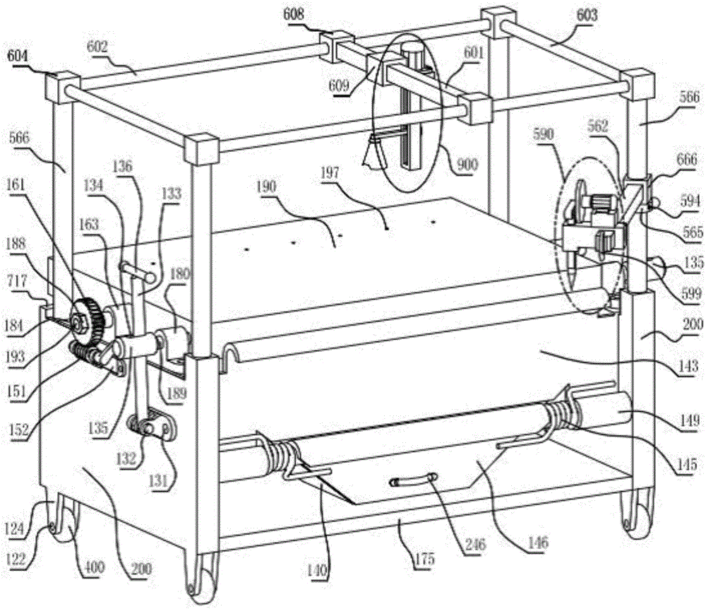
[0069] figure 1 , figure 2 , Figure 5 , Figure 10 , Figure 11 , Figure 12 , Figure 13 , Figure 14 , Figure 15 and Figure 17 In the glass inspection frame, the whole frame includes a supporting side plate 200, a rear shearing plate 176, a bottom shearing plate 175 and four upper circular columns 566. The supporting side plates 200 on both sides are respectively fixed with the two mentioned The upper circular column 566, the upper ends of the four upper circular columns 566 are all fixed with column ends 604, and the four column ends 604 are respectively fixed with two horizontal horizontal rods 602 and two longitudinal horizontal rods 603;

[0070] The upper planes of the supporting side plates 200 described on both sides are respectively fixed with the platen support 163 and the lock pin support 180; the test platen 190 has ...


PUM

PropertyMeasurementUnit
thicknessaaaaaaaaaa
tensile strengthaaaaaaaaaa
widthaaaaaaaaaa

Abstract

The invention relates to a toughened glass test rack, in particular to a glass detecting rack. As improvement, the glass detecting rack is characterized in that a transmission worm is matched with a worm shaft; the two ends of the worm shaft can be rotatably fixed in worm supporting bases separately; the worm supporting bases are fixedly arranged on the outer side surface of a corresponding supporting side plate; one end of the worm shaft is further provided with a worm cranking handle; a screw lifting camera group is arranged on a camera shooting square rod; a rotary impactor can be fixedly arranged on an impact cross rod in a sliding manner; a step corner pressure plate assembly comprises a first pressure plate, a second pressure plate, a third pressure plate and a fourth pressure plate which are the same in structural dimension; and each pressure plate is composed of a clamping part and a sliding corner part. According to the glass detecting rack, labor intensity of fragment detecting is changed, camera shooting is carried out, and fragment images are transmitted to a computer processing center; the rotary impactor is applied, so that hammering every time is consistent is force, and therefore, breaking test specifications are unified.

Description

technical field [0001] The invention relates to a toughened glass test and inspection frame, in particular to a glass inspection frame equipped with an industrial camera instead of manual operation and a detection method thereof. Background technique [0002] Gordon GaileG published an article "Automated Glass Fragmentation Analysis" in 1996, which discussed the detection algorithm of glass fragments. This document involves two key technologies: (1) image acquisition technology. Under a piece of photosensitive paper imaged by glass shards, light sources were applied from two different angles, and an original digital image of the shadow of the crack line of the shards was collected. In this way, due to the use of light sources at different angles, the two images collected must be different. In one of the images, the position of the inconspicuous seam line due to lighting may be more obvious in the other image. Therefore, when the two images are combined at an appropriate ti...

Claims


Application Information

Patent Timeline
Patent Type & Authority Applications(China)
IPC IPC(8): G01N3/34G01N21/84
CPCG01N3/34G01N21/84
Inventor 徐明
Owner 徐明
Why Eureka
Try Eureka