Skull lock

A skull and clavicle technology, applied in the field of cranial locks, can solve problems such as inconvenient use and complex structure, and achieve the effect of firm fixation, good biocompatibility, and simple structure

Inactive Publication Date: 2016-07-20
周倩
View PDF9 Cites 11 Cited by
  • Summary
  • Abstract
  • Description
  • Claims
  • Application Information

AI Technical Summary

Problems solved by technology

[0004] The purpose of the present invention is to provide a skull lock, which can solve the disadvantages of inconvenient use and complex structure in the prior art

Method used


Image

  • Skull lock
  • Skull lock
  • Skull lock

Examples


Embodiment Construction

[0019] Further elaborate the present invention below in conjunction with specific embodiment

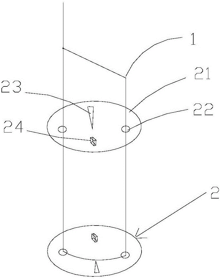
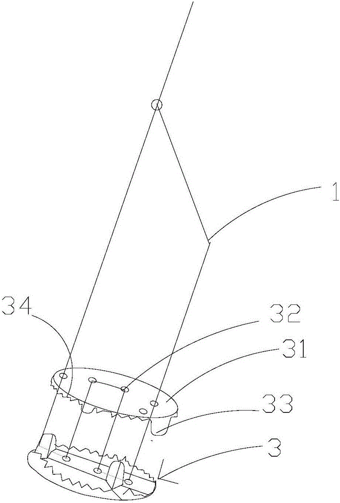
[0020] The invention discloses a skull lock, which includes a skull lock flap 2, and the skull lock flap includes a flap body 21, and the flap body is provided with several wire holes 22, grooves 23 and teeth post 24, and the groove 23 is formed by the downward depression of the flap body 21, and the tooth post 24 is formed by the upward protrusion of the flap body 21, and the tooth post 24 can be fixed on the skull and Prevent slipping. The present invention also includes a suture 1, and the suture 1 can pass through the thread hole 22, and one end of the suture passing through the thread hole and one end not passing through the thread hole can be tied and fixed.

[0021] The suture of the present invention is a PPDO absorbable suture, which is a single-strand structure absorbable suture spun from polydioxanone (PPDO) material, and has good physical and mechanical strength and chem...


PUM


Abstract

The invention discloses a skull lock which comprises a skull lock valve slice, the skull lock valve slice comprises a valve slice main body, the valve slice main body is provided with a plurality of thread holes, a groove and a tooth column, the groove is formed in the mode that the valve slice main body is downwards sunken, the tooth column is formed in the mode that the valve slice main body is upwards protruded, and the tooth column can be fixed to a skull and is prevented from sliding.The skull lock is simple in structure, firm in fixation, controllable in degradation velocity and good in biocompatibility.

Description

technical field [0001] The invention relates to the field of biomaterials, more specifically a skull lock. Background technique [0002] Craniotomy free bone flap forming is a common basic operation in neurosurgery, and it is a necessary step for intracranial operation. Except for some cases of intracranial hypertension that require decompressive craniectomy, in most cases, the free bone flap needs to be reset and fixed after the intracranial operation is completed, so as to restore the integrity of the skull to the maximum extent, maintain the balance and stability of intracranial pressure, and protect brain tissue , to avoid two-stage cranioplasty. When the free bone flap is reset, it needs to be fixed on the surrounding skull with the help of instruments to prevent the bone flap from shifting or pulsating with the brain tissue. [0003] The ideal cranial bone flap fixation material and technique should have the following characteristics: 1) safe in clinical use; 2) good...

Claims


Application Information

Patent Timeline
Patent Type & Authority Applications(China)
IPC IPC(8): A61B17/80
CPCA61B17/688A61B17/8085
Inventor 周倩蒋宇钢
Owner 周倩
Why Eureka
Try Eureka