Disinfecting cabinet and disinfecting factor generating device thereof

A technology of generating device and disinfection cabinet, which is applied in irradiation and other directions, can solve the problems of dead angle in irradiation and heating, poor disinfection effect, and low heating efficiency, and achieve the effect of high heating efficiency, good drying effect and uniform temperature

Inactive Publication Date: 2016-07-20
GUANGDONG SUKI IND CO LTD
View PDF5 Cites 6 Cited by
  • Summary
  • Abstract
  • Description
  • Claims
  • Application Information

AI Technical Summary

Problems solved by technology

[0002] With the continuous improvement of people's living standards, while paying attention to physical health, the requirements for sanitary conditions are also getting higher and higher, making tableware disinfection cabinets become indispensable electrical equipment for families and catering industries. The devices are generally installed at the back or top of the cabinet. For a disinfection cabinet with two drawers, there are two layers of dish racks in the inner room. When the tableware is fully loaded, the tableware in the front or lower part of the cabinet cannot be irradiated. There are dead angles, the ultraviolet light cannot directly shine on the tableware, and there are problems of low heating efficiency, long time, high energy consumption, and poor disinfection effect; based on the above reasons, it is necessary to carry out technical improvement and improvement on the tableware disinfection cabinet of the prior art to provide a A disinfection cabinet with comprehensive and thorough disinfection, uniform drying, high disinfection efficiency and low energy consumption

Method used


Image

  • Disinfecting cabinet and disinfecting factor generating device thereof
  • Disinfecting cabinet and disinfecting factor generating device thereof
  • Disinfecting cabinet and disinfecting factor generating device thereof

Examples


Embodiment Construction

[0020] The following will clearly and completely describe the technical solutions in the embodiments of the present invention with reference to the accompanying drawings in the embodiments of the present invention. Obviously, the described embodiments are only some, not all, embodiments of the present invention. Based on the embodiments of the present invention, all other embodiments obtained by persons of ordinary skill in the art without making creative efforts belong to the protection scope of the present invention.

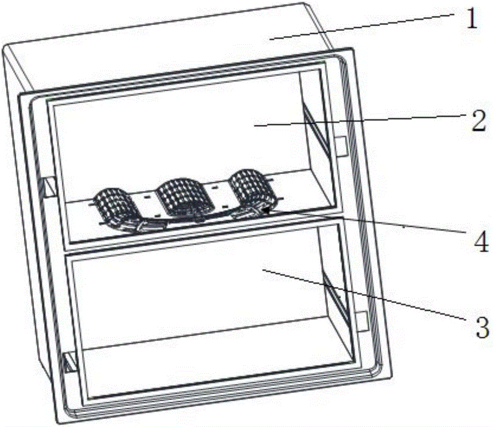
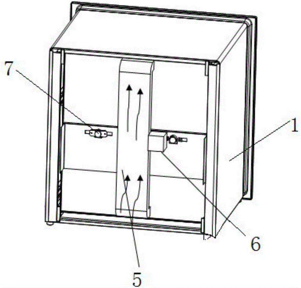
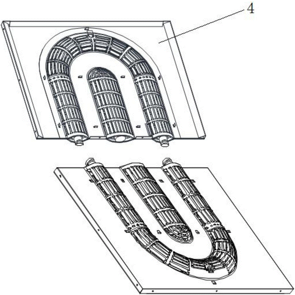
[0021] see Figures 1 to 7 , in an embodiment of the present invention, a disinfection cabinet and a disinfection factor generating device thereof include a cabinet body 1, an inner tank is arranged in the cabinet body 1, and the inner tank is divided into an upper layer 2 and a lower layer 3, and a space between the upper layer 2 and the lower layer 3 A disinfection factor generating device 4 is installed on the center beam, which can effectively use the spac...


PUM


Abstract

The invention discloses a disinfecting cabinet and a disinfecting factor generating device thereof. The disinfecting cabinet comprises a cabinet body, the disinfecting factor generating device is mounted on a middle beam between the upper layer and the lower layer of the cabinet body, the disinfecting factor generating device comprises an upper reflective light guide plate, a sterilizing lamp and a lower light guide protection cover, the sterilizing lamp is arranged between the upper reflective light guide plate and the lower light guide protection cover, a second fixing member sleeves the sterilizing lamp and is fixedly connected with the upper reflective light guide plate, the upper reflective light guide plate and the lower light guide protection cover are arranged in a clamped connection manner, the sterilizing lamp is one of or a combination of several of a light wave sterilizing lamp or an ultraviolet sterilizing lamp or other heating tubes or a metal halogen lamp, and the sterilizing lamp is arranged to be U-shaped or annular or S-shaped.Omnibearing irradiation sterilizing and heating are realized upper-lower irradiation and heating distribution control, so that effective using space is increased, sterilizing range is widened, sterilizing efficiency is improved, and the disinfecting cabinet is uniform and efficient in heating and drying, comprehensive and thorough in sterilizing and more energy-saving and power-saving.

Description

technical field [0001] The invention relates to the field of disinfection equipment, in particular to a disinfection cabinet and a disinfection factor generating device thereof. Background technique [0002] With the continuous improvement of people's living standards, while paying attention to physical health, the requirements for sanitary conditions are also getting higher and higher, making tableware disinfection cabinets become indispensable electrical equipment for families and catering industries. The devices are generally installed at the back or top of the cabinet. For a disinfection cabinet with two layers of drawers, there are two layers of dish racks in the inner room. When the tableware is fully loaded, the tableware in the front or lower part of the cabinet cannot be irradiated. There are dead angles, the ultraviolet light cannot directly shine on the tableware, and there are problems of low heating efficiency, long time, high energy consumption, and poor disinf...

Claims


Application Information

Patent Timeline
Patent Type & Authority Applications(China)
IPC IPC(8): A61L2/08A61L2/10
CPCA61L2/08A61L2/10
Inventor 刘澄胡存超
Owner GUANGDONG SUKI IND CO LTD
Why Eureka
Try Eureka