A Tension Structure for Reducing Disturbance Loss

A technology of rib structure and rib, applied in the direction of blade supporting elements, engine elements, machines/engines, etc., can solve the problems of reducing the operating efficiency of turbomachinery, increasing the additional mass of the blade, affecting the safe operation of the blade, etc., so as to improve the safety Effect of running margin, reducing added mass, reducing angle of attack loss

Active Publication Date: 2017-10-20
XI AN JIAOTONG UNIV
View PDF6 Cites 0 Cited by
  • Summary
  • Abstract
  • Description
  • Claims
  • Application Information

AI Technical Summary

Problems solved by technology

There is a reverse pressure gradient near the surface of the damping lacing structure, which leads to flow separation of the fluid on the surface of the lacing, and the shedding of the wake vortex will cause a large disturbance to the flow field; at the same time, the leading edge of the damping lacing structure produces flow resistance, which inevitably causes The additional flow loss, which greatly reduces the operating efficiency of the turbomachinery, so how to reduce the flow loss of the turbomachinery caused by the tension has been widely concerned by scholars at home and abroad
In addition, the use of damping tendons, especially for long blades subject to a large excitation force, in order to better suppress the vibration, the size of the damping tendons will inevitably increase accordingly, which will not only affect the stability of the flow field, but also lead to additional blades. The increase in mass, thus increasing the centrifugal load, affects the safe operation of the blade

Method used


Image

  • A Tension Structure for Reducing Disturbance Loss
  • A Tension Structure for Reducing Disturbance Loss
  • A Tension Structure for Reducing Disturbance Loss

Examples


Embodiment Construction

[0023] The present invention will be further described below in conjunction with accompanying drawing.

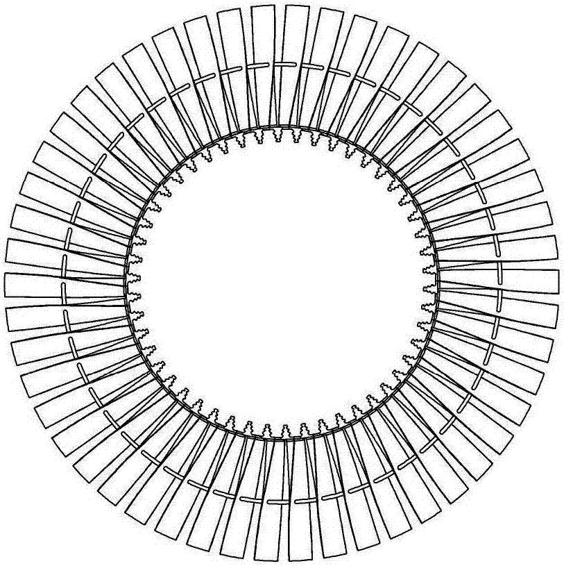
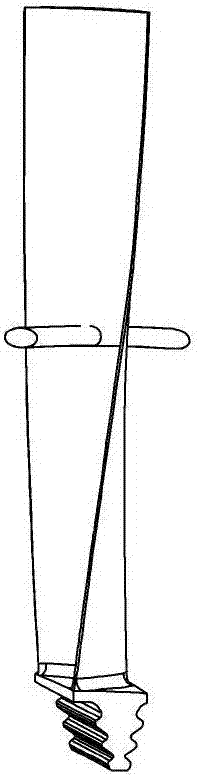
[0024] refer to figure 1 , figure 2 As shown in Fig. 1, the structure of the rotating damping vane with damping ties and the structure of a single damping vane are given respectively. The damping blade includes a blade body, a blade root and a damping tendon structure.

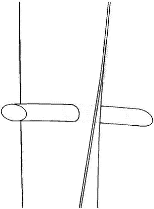
[0025] refer to Figure 3a , Figure 3b As shown, the conventional damping tendon structure and the damping tendon structure of the present invention are respectively provided. The invention provides a wedge-shaped or rectangular channel on the basis of the conventional damping tendon structure. The main airflow flows downstream through the tendons, and another small part of the airflow passes through the wedge-shaped or rectangular channels of the tendon structure, and merges into the main flow by means of synthetic jets, so as to inject high-energy fluid into the tail low-energy fluid area around th...


PUM


Abstract

The invention discloses a tie piece structure for reducing turbulent flow losses. A wedge-shaped groove channel or a rectangular groove channel is formed in the position of an airflow front stagnation point of the tie piece structure in the radial direction of the tie piece structure, wherein the tie piece structure is an annular structure with the cross section being cylindrical or elliptical; the grooving length L of the tie piece structure is equal to 0.05R to 0.15 R, and R is the radius of a tie piece or half of a short axis of an ellipse; the wedge-shaped inclination angle alpha is equal to 0.3 degree, and when alpha is equal to 0 degree, the rectangular groove channel is formed. According to the tie piece structure, by means of grooving of the tie piece, high-energy fluid is injected into a low-energy fluid region at the tail of the tie piece in a synthetic jet flow manner, and therefore the capacity of the tie piece for resisting the adverse pressure gradient is improved, and the tail vortex-shedding inhibition degree is improved; meanwhile, because the groove is formed in the position of the airflow front stagnation point of the tie piece, the tie piece flowing resistance is reduced to a great extent, and the efficiency of turbine blades is effectively improved; and the tie piece structure reduces the additional mass of the blades at the same time so that additional centrifugal force loads can be reduced, and the safe running margin is effectively improved.

Description

Technical field: [0001] The invention belongs to the field of turbomachinery, and in particular relates to a lacing structure for reducing turbulence loss. Background technique: [0002] Turbomachinery is a power machine that uses continuously flowing fluid as the working medium and converts fluid energy into mechanical energy through the interaction with the blades. It is the core component of the energy power system and is indispensable in the national economy and national defense. missing component. Blades play a vital role in energy conversion, so their safety and efficiency have always attracted attention in the entire energy and chemical industry. [0003] Turbine blades will be subjected to the exciting force of the airflow during work, resulting in blade vibration, and the key measures to reduce blade vibration mainly include two aspects: (1) Consider the frequency avoidance rate to avoid resonance; (2) Adopt the blade damping structure , such as damping bosses, da...

Claims


Application Information

Patent Timeline
Patent Type & Authority Patents(China)
IPC IPC(8): F01D5/16
CPCF01D5/141F01D5/16
Inventor 谢永慧高科科张荻
Owner XI AN JIAOTONG UNIV
Why Eureka
Try Eureka