Tap water pipeline water flow self- power generation device and use method thereof

A power generation device, tap water technology, applied in the direction of hydropower, engine components, machines/engines, etc., can solve the problem that the power supply of the micro-generator cannot meet the power consumption of the solenoid valve, affect the accuracy of water meter measurement, and measure the water meter, etc. The effect of small voltage drop, low power consumption, effective and reasonable resources

Inactive Publication Date: 2016-07-20
辽宁鑫洪源科技有限公司
View PDF9 Cites 1 Cited by
  • Summary
  • Abstract
  • Description
  • Claims
  • Application Information

AI Technical Summary

Problems solved by technology

The main reason why it cannot be used to measure water meters is the problem of water leakage
[0005] Among the existing patents, the application number is: 200710186881.0, which discloses a self-powered automatic meter reading and remote water cut-off intelligent water meter. Supplying micro-generators for power generation affects the accuracy of water meter measurement; at the same time, the power supply of micro-generators cannot meet the power consumption of solenoid valves, drive circuits, power supplies, etc.
The same application number: 201310406324.0, discloses a prepaid smart water meter based on self-flowing water power supply, which also affects the accuracy of water meter measurement

Method used


Image

  • Tap water pipeline water flow self- power generation device and use method thereof
  • Tap water pipeline water flow self- power generation device and use method thereof
  • Tap water pipeline water flow self- power generation device and use method thereof

Examples


Embodiment Construction

[0027] The present invention will be described in detail below in conjunction with the accompanying drawings, but it should be pointed out that the implementation of the present invention is not limited to the following embodiments.

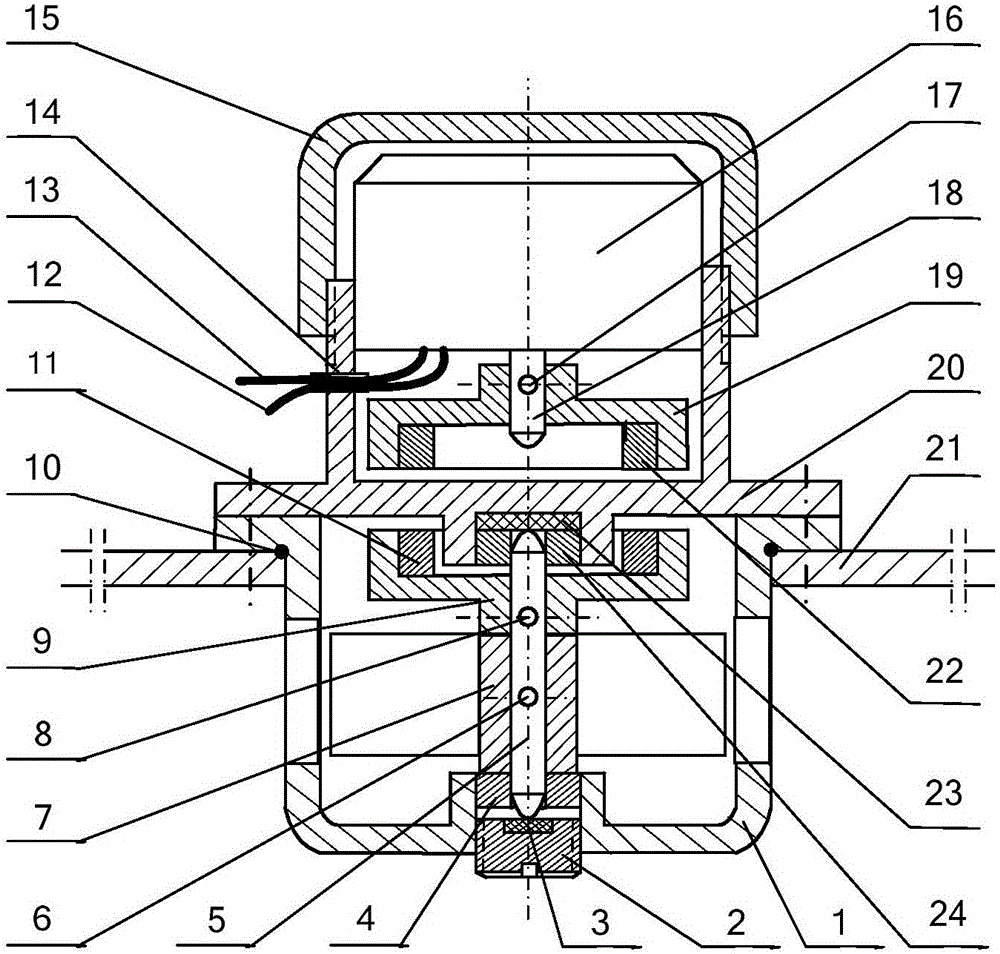
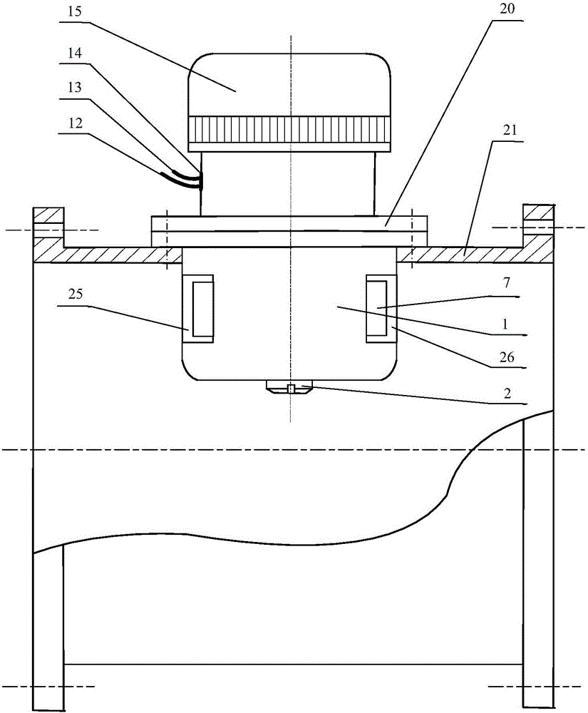
[0028] See Figure 1-Figure 3 , a self-generating device for the water flow of the water pipe 21, the power generating device is arranged on the water pipe 21, behind the metering water meter, the tap water is supplied to the user after the metering water meter and the power generating device, this kind of setting may not affect the normal operation of the metering water meter, Does not affect the accuracy of measurement. The device includes a generator 16, an upper magnet cup 19, an upper magnet ring 22, a lower magnet cup 9, a lower magnet ring 11, a generator seat 20, an impeller 7, an impeller shaft 5, an impeller 7 support 1, and an upper radial bearing 24 , lower radial bearing 4, adjusting screw 2; generator 16, upper magnet cup 19, upper...


PUM


Abstract

The invention relates to a tap water pipeline water flow self- power generation device and a use method thereof. The power generation device is arranged on a tap water pipeline behind a water meter; and tap water passes by the measurement water meter and the power generation device to be supplied to users. The tap water pipeline water flow self- power generation device comprises a power generator, an upper magnet cup, an upper magnetic ring, a lower magnet cup, a lower magnetic ring, a power generator base, an impeller, an impeller shaft, an impeller support, an upper radial bearing, a lower radial bearing and an adjusting screw, wherein a power generator shaft is fixedly connected with the upper magnet cup; the upper magnetic ring is axially arranged in the upper magnet cup; the impeller support is fixedly connected with the power generator base; the parts, which correspond to the impeller, of the impeller support are provided with a water inlet and a water outlet; the lower magnet cup is fixedly connected with the impeller shaft; and the upper magnetic ring corresponds to the lower magnetic ring. The tap water pipeline water flow self- power generation device has the advantages that by utilizing the tap water pipeline water flow self- power generation device, power can be continuously provided for the water meter; self-power generation is realized by utilizing a tap water pipeline water flow; and magnetic coupling and noncontact transmission are adopted between the impeller in a pipeline containing water and the power generator outside the pipeline, so that the power generator is isolated from water.

Description

technical field [0001] The invention relates to a water flow self-generating device for a tap water pipeline and a use method thereof. Background technique [0002] With the development of the economy and the increase of the population, the human demand for water resources continues to increase, coupled with the unreasonable exploitation and utilization of water resources, many countries and regions have different degrees of water shortage problems. This phenomenon is called Water shortages. Tap water is an indispensable material in human life, and tap water supply is even more tense in the world. [0003] Tap water is natural water that can only be used after special treatment. The treatment process also needs to consume a lot of manpower and material resources, especially a large amount of energy. Therefore, metering is required in multiple water use processes. For example, each user's water consumption is equipped with a water meter. Currently, each user's water meter...

Claims


Application Information

Patent Timeline
Patent Type & Authority Applications(China)
IPC IPC(8): F03B13/00F03B11/00F03B11/06
CPCF03B11/00F03B11/06F03B13/00Y02E10/20
Inventor 武景新王春岩
Owner 辽宁鑫洪源科技有限公司
Why Eureka
Try Eureka