Plug-in type gas blaster igniter and cracking device

A technology for detonating device and blaster, which is applied to valve devices, blasting cylinders, compressed gas generation and other directions, can solve the problems of high manufacturing cost, low heat release efficiency, long time consumption, etc., and achieves high mixing uniformity and heat release effect.

Inactive Publication Date: 2017-05-10
郭远军
View PDF1 Cites 0 Cited by
  • Summary
  • Abstract
  • Description
  • Claims
  • Application Information

AI Technical Summary

Problems solved by technology

[0006] The detonating device with the above structure has the following problems: 1. The thermal reactants to be filled in the detonating device need to be processed by mixing, mixing, coiling or bagging, and the filling process is time-consuming. 2. During the filling process of the detonating device, the oxidant and reductant are prone to uneven mixing, resulting in low heat release efficiency; 3. The thermal reaction material needs to be mixed and filled in advance, and the temperature is too high during transportation. It is highly likely to cause combustion or explosion, and has a greater potential safety hazard; 4. Due to the delay of the detonating material or other situations, it is easy to appear the situation of squibs, and it is impossible to judge the cause of the squibs, so it cannot be eliminated by rowing the squibs Potential safety hazard; 5. The existing gas blaster detonation method uses a solid activator to burn to generate high temperature, which directly conducts heat to liquid carbon dioxide, causing the liquid carbon dioxide to gasify and expand, and its heat absorption efficiency of liquid carbon dioxide is low
[0007] In addition, since the lead wire of the conventional detonator contains two exposed terminals, the wiring needs to be connected separately, and the wiring process takes a long time; in addition, the exposed terminals are prone to the risk of electrostatic contact, and there is a risk of electrostatic detonation

Method used


Image

  • Plug-in type gas blaster igniter and cracking device
  • Plug-in type gas blaster igniter and cracking device
  • Plug-in type gas blaster igniter and cracking device

Examples


Embodiment 1

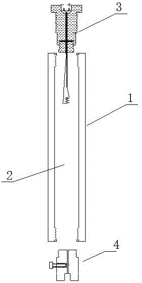
[0066] A plug-in gas blaster detonating device, such as figure 1 As shown, it includes a housing 1, a filling chamber 2, an ignition mechanism 3 and an inflatable mechanism 4. The housing 1 is filled with a chamber 2, and the housing 1 is sealed to connect the ignition mechanism 3 and the inflatable mechanism 4. The pressure resistance of the housing 1 The strength is greater than 5.045Mpa; the shell 1 is a carbon steel cylinder or a stainless steel cylinder, and the inflation mechanism 4 and the ignition mechanism 3 are respectively connected to both ends of the shell 1;

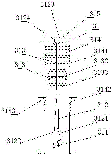
[0067] Such as figure 2 As shown, the ignition mechanism 3 includes a heating wire 311, a wire 312, a wire through hole 313, a sealing base 314 and a socket 315, the heating wire 311 is connected to the wire 312, the axial center of the sealing base 314 is a wire through hole 313, and the plugging groove 315 is located on the upper part of the wire through hole 313, and the positive pole pin 3151 and the ...

Embodiment 2

[0073] The difference with embodiment 1 is: as Figure 4 As shown, the housing 1 includes a first segment body 11 and a second segment body 12, the first segment body 11 and the second segment body 12 are connected through a threaded structure, and are matched with a threaded sealing ring 13 for Sealing; the inflation mechanism 4 and the ignition mechanism 3 are respectively connected to both sides of the first segment body 11 and the second segment body 11; this structure is convenient for charging.

Embodiment 3

[0075] The difference with embodiment 1 is: as Figure 5As shown, the housing 1 is a composite layer tube containing fiber material, the housing 1 is made of composite layers, the housing 1 includes a matrix layer 101, a fiber layer 102 and a hardened layer 103, and the hardened layer 103 is located at The outer layer of the fiber layer 102, the matrix layer 101 is located in the inner layer of the fiber layer 102; the two ends of the housing 1 are respectively sealed and wrapped with a first metal joint 111 and a second metal joint 112, and the first metal joint 111 and the second metal joint 112 are sealed and wrapped respectively. Two metal joints 112 are respectively connected to the inflation mechanism 4 and the ignition mechanism 3 ;

[0076] As a further description of the above embodiment, the base layer 101 is made of polyethylene (PE); the fiber layer 102 is made of glass fiber; the hardened layer 103 is made of epoxy resin.

[0077] As a further description of the ...


PUM

PropertyMeasurementUnit
Compressive strengthaaaaaaaaaa
Thicknessaaaaaaaaaa
Inner diameteraaaaaaaaaa

Abstract

The invention discloses a plug-in type gas blaster igniter and a cracking device. The plug-in type gas blaster igniter comprises a shell, a filling cavity, an ignition mechanism and an inflation mechanism, the filling cavity is formed in the shell, the shell is connected with and seals the ignition mechanism and the inflation mechanism, the ignition mechanism comprises an electric heating wire, a wire, a wire punched hole, a seal substrate and a plug-in slot, the electric heating wire is connected with the wire, the axial core of the seal substrate is the wire punched hole, the plug-in slot is located in the upper portion of the wire punched hole, a positive pin and a negative pin are installed inside the plug-in slot, a positive wire body and a negative wire body of the wire penetrate through the wire punched hole to be connected with the positive pin and the negative pin respectively, one end of the wire punched hole is an internal thread hole, an internal seal rubber gasket is installed at the bottom of the internal thread hole which cooperates with a punched hole screw, the axis of the punched hole screw is provided with a punched hole, the wire penetrates through the internal seal rubber gasket and the punched hole screw, the punched hole screw cooperates with the internal thread hole to compress the internal seal rubber gasket, and the wire is sealed; the plug-in type gas blaster igniter has the advantages of being low in manufacturing cost, high in reactant mixing uniformity, high in heat release efficiency and good in transport safety.

Description

technical field [0001] The invention belongs to the field of detonating devices, in particular to a detonating device for a plug-in gas blaster. Background technique [0002] Gas blasting technology is to use the vaporization and expansion of easily vaporized liquid or solid substances to generate high-pressure gas, which makes the surrounding medium expand to do work and cause fragmentation. It has the characteristics of no open flame, safety and high efficiency. [0003] Carbon dioxide gas blasters are typical blasting equipment in gas blasting technology, and are widely used in mining, geological exploration, cement, steel, electric power and other industries, subways and tunnels, municipal engineering, underwater engineering, and emergency rescue. [0004] Existing gas blasters mainly include a vaporization liquid storage pipe and a heating detonator installed in the vaporization liquid storage pipe; the heating detonation device ignites and generates heat to vaporize ea...

Claims


Application Information

Patent Timeline
IPC IPC(8): F42B3/04F42B3/10F42B3/103F42B3/11F42B3/18C06D5/10C06B33/00C06B47/12C06B47/06C06B47/02C06B27/00F16K15/02F16K24/06
CPCC06B27/00C06B33/00C06B47/02C06B47/06C06B47/12C06D5/10F16K15/02F16K24/06F42B3/045F42B3/10F42B3/103F42B3/11F42B3/18Y02P20/10
Inventor 郭远军
Owner 郭远军
Why Eureka
Try Eureka