Wind driven generator yawing device with locking function

A wind turbine and locking mechanism technology, applied in wind turbines, wind power generation, engines, etc., can solve the problems of increasing the energy consumption rate of wind turbines, complicated processing technology of large-diameter bearings, and increasing the cost of wind turbines. Achieve the effect of saving energy consumption, protecting the safety of the fan, and stabilizing the structure

Active Publication Date: 2016-07-20
HEBEI UNIV OF TECH
View PDF5 Cites 4 Cited by
  • Summary
  • Abstract
  • Description
  • Claims
  • Application Information

AI Technical Summary

Problems solved by technology

[0002] With the continuous development and application of wind energy technology, the cost of wind turbines and the utilization rate of wind energy by wind turbines have become research hotspots. Through analysis, there are still many problems in the yaw device of wind turbines that need to be improved. The yaw device in the generator needs a bearing with a larger diameter to cooperate with the tower. Because the processing technology of the large-diameter bearing is relatively complicated, this greatly increases the cost of the wind turbine. In addition, the existing large wind turbines are equipped with Multiple yaw motors, when the yaw reaches an appropriate angle, the yaw motor performs electric braking to make the sweeping surface of the impeller face the wind direction, which consumes a part of electric energy, which greatly increases the energy consumption rate of the wind turbine itself, so Optimizing the design of the hub will be of great significance to improving economic benefits

Method used


Image

  • Wind driven generator yawing device with locking function
  • Wind driven generator yawing device with locking function
  • Wind driven generator yawing device with locking function

Examples


Embodiment Construction

[0028] Describe the present invention in detail below in conjunction with embodiment and accompanying drawing. The embodiment is based on the specific implementation carried out on the premise of the technical solution of the present invention, and provides detailed implementation methods and processes. However, the protection scope of the claims of the present application is not limited to the description of the following embodiments.

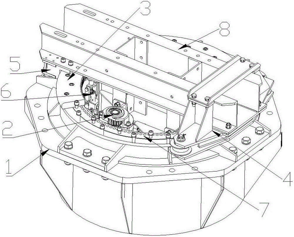
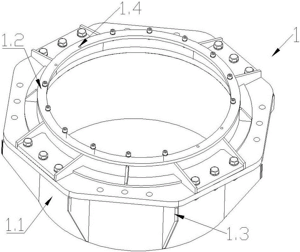
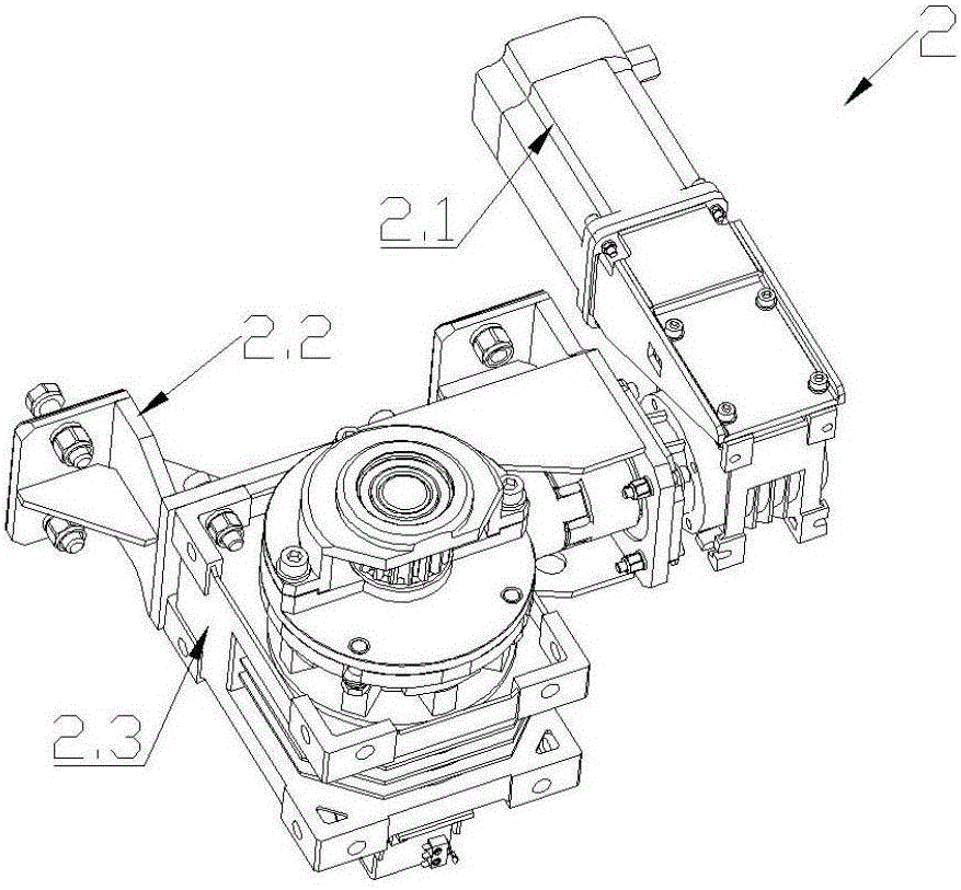
[0029] The wind power generator yaw device with locking function of the present invention (referred to as yaw device, see Figure 1-9 ) includes a tower mechanism 1, a yaw driving mechanism 2, a transmission inner ring gear 3, a ring gear matching supporting wheel frame 4, a ring gear matching adjusting wheel frame 5, a locking mechanism 6, a locking chuck 7 and a nacelle supporting frame 8 ;

[0030] Described nacelle bracing frame 8 (referring to Figure 9 ) includes engine room support frame crossbeam 8.1, engine room support frame conne...


PUM


Abstract

The invention relates to a wind driven generator yawing device with a locking function. The wind driven generator yawing device is characterized by comprising a tower drum mechanism, a yaw driving mechanism, a transmission inner gear ring, a gear ring cooperation supporting wheel carrier, a gear ring cooperation adjusting wheel carrier, a locking mechanism, a locking chuck and an engine room support frame, wherein the engine room support frame comprises engine room support frame cross beams, an engine room support frame connecting plate, engine room support frame vertical beams and a locking mechanism connecting plate; the middle parts of the two engine room support frame cross beams are connected with the two engine room support frame vertical beams; the engine room support frame connecting plate is connected between the lower ends of the two engine room support frame vertical beams; the locking mechanism connecting plate is arranged on the side surface of one engine room support frame vertical beam; the upper end of the tower drum mechanism is fixedly connected with the transmission inner gear ring and the locking chuck; the locking chuck is arranged below the transmission inner gear ring; the yaw driving mechanism is fixedly connected on the engine room support frame connecting plate; and the locking mechanism is fixed to the locking mechanism connecting plate.

Description

technical field [0001] The invention relates to the technical field of wind power generator transmission, in particular to a wind power generator yaw device with a locking function. Background technique [0002] With the continuous development and application of wind energy technology, the cost of wind turbines and the utilization rate of wind energy by wind turbines have become research hotspots. Through analysis, there are still many problems in the yaw device of wind turbines that need to be improved. The yaw device in the generator needs a bearing with a larger diameter to cooperate with the tower. Because the processing technology of the large-diameter bearing is relatively complicated, this greatly increases the cost of the wind turbine. In addition, the existing large wind turbines are equipped with Multiple yaw motors, when the yaw reaches an appropriate angle, the yaw motor performs electric braking to make the sweeping surface of the impeller face the wind directio...

Claims


Application Information

Patent Timeline
Patent Type & Authority Applications(China)
IPC IPC(8): F03D80/00
CPCY02E10/72
Inventor 宋中越沈昭仰甄冬张浩师占群
Owner HEBEI UNIV OF TECH
Why Eureka
Try Eureka