Rapid three-phase voltage phase-locked loop method and dynamic response performance analyzing method thereof
A three-phase voltage and analysis method technology, applied in instruments, control/regulation systems, simulators, etc., can solve problems such as insufficient frequency adaptability, complex implementation, and difficult parameter design.
- Summary
- Abstract
- Description
- Claims
- Application Information
AI Technical Summary
Problems solved by technology
Method used
Image
Examples
Embodiment 1
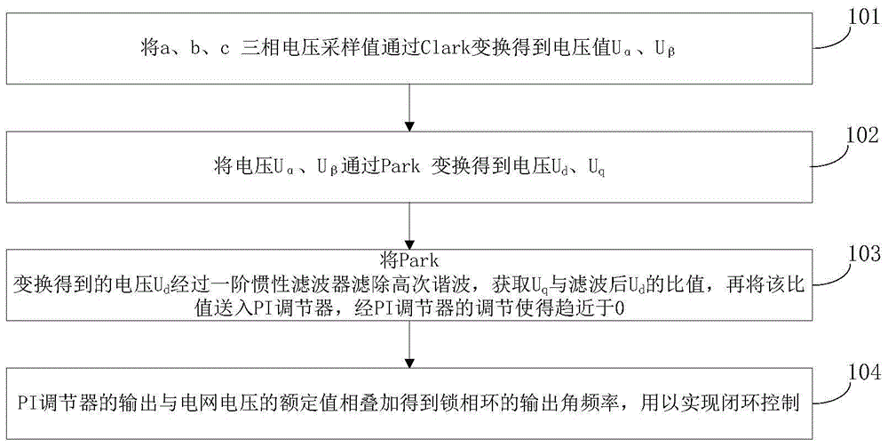
[0064] see figure 1 , Embodiment 1 provides a fast three-phase voltage phase-locked loop method, comprising the following steps:
[0065] 101. The three-phase voltage sampling value U of a, b, and c a , U b and U c The voltage U is obtained by Clark transformation α , U β .
[0066] 102. The voltage U obtained in step 101 α , U β The voltage U is obtained by Park transformation d , U q , U d is the reactive component, U q is the active component.
[0067] 103. The voltage U obtained by Park transformation in step 102 d After the first-order inertial filter filters out the high-order harmonics, the U q and filtered U d The ratio U q / U d , then U q / U d sent to the PI regulator, and adjusted by the PI regulator to make U q / U d tends to 0. Wherein, the filtering method and transfer function of the first-order inertial filter are well known to those skilled in the art, so detailed description is omitted.
[0068] 104. Adjust U in step 103 q / U d When it ...
Embodiment 2
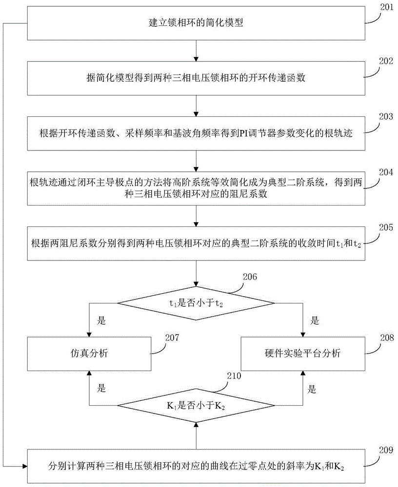
[0081] see figure 2 , embodiment 2 provides the dynamic response performance analysis method of the fast three-phase voltage phase-locked loop method that embodiment 1 provides, and this analysis method comprises the following steps:
[0082] 201. Establish a simplified model of a three-phase voltage phase-locked loop.
[0083] Wherein, step 201 specifically includes:
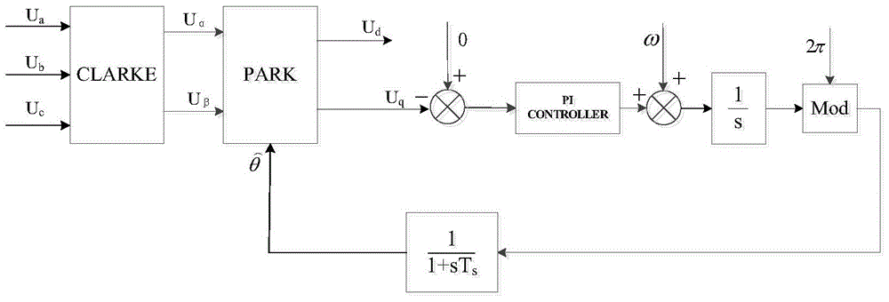
[0084] (1) see Figure 5 , to establish a simplified mathematical model of a three-phase voltage phase-locked loop.
[0085] Among them, both the traditional three-phase voltage phase-locked loop and the high-speed three-phase voltage phase-locked loop adopt the above-mentioned model.
[0086] Among them, in the above model, the F of the traditional three-phase voltage phase-locked loop 1 (θ)=sinΔθ, F of the high-speed phase-locked loop 2 (θ) = tanΔθ.
[0087] (2) see Figure 6 , according to the simplified mathematical model of the three-phase voltage phase-locked loop established in step (1), the frequen...
Embodiment 3
[0110] Embodiment 3 discloses the basic structure and principle of the traditional phase-locking method. Assume that the grid voltage is a three-phase balanced voltage amplitude of U m , the fundamental angular frequency is ω 0 , the initial phase angle of phase A voltage is 0, then the three-phase grid voltage can be expressed as the following formula.
[0111]
[0112] Assuming that the initial actual angle of the grid voltage vector is θ, the three-phase grid voltage is transformed from a three-phase static coordinate system to a two-phase static coordinate system through Clarke transformation, and then oriented by the D axis, and the phase-locked loop outputs the phase angle Perform Park transformation for the rotation angle, transform the two-phase stationary coordinate system into the synchronously rotating dq coordinate system, and the following formula can be obtained.
[0113]
[0114]
[0115] In order to further simplify the above two formulas, set the e...
PUM
 Abstract
Description
Claims
Application Information
 - R&D
- Intellectual Property
- Life Sciences
- Materials
- Tech Scout
- Unparalleled Data Quality
- Higher Quality Content
- 60% Fewer Hallucinations
Browse by: Latest US Patents, China's latest patents, Technical Efficacy Thesaurus, Application Domain, Technology Topic, Popular Technical Reports.
© 2025 PatSnap. All rights reserved.Legal|Privacy policy|Modern Slavery Act Transparency Statement|Sitemap|About US| Contact US: help@patsnap.com


