Control rod driving mechanism of floating type reactor

A floating reactor and driving mechanism technology, applied in the control of nuclear reactions, reactors, reducing greenhouse gases, etc., can solve problems such as wear, complex contact conditions, and difficulty in re-engaging the roller nut and the lead screw, and achieve precise operation High strength, simple and easy structure, and reliable mechanism transmission action

Pending Publication Date: 2016-07-20
SHANGHAI NUCLEAR ENG RES & DESIGN INST CO LTD +1
View PDF8 Cites 15 Cited by
  • Summary
  • Abstract
  • Description
  • Claims
  • Application Information

AI Technical Summary

Problems solved by technology

If the connection is re-established, a deviation in relative position will be introduced, which will make the re-engagement of the roller nut and the lead screw m

Method used


Image

  • Control rod driving mechanism of floating type reactor
  • Control rod driving mechanism of floating type reactor
  • Control rod driving mechanism of floating type reactor

Examples


Embodiment Construction

[0026] In order to make the above objects, features and advantages of the present invention more comprehensible, the present invention will be further described in detail below in conjunction with the accompanying drawings and specific embodiments.

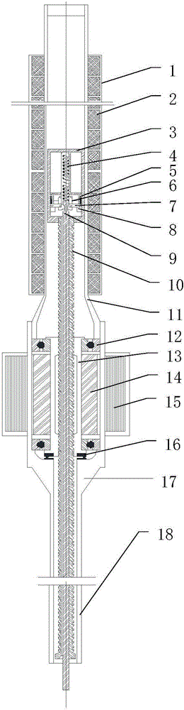
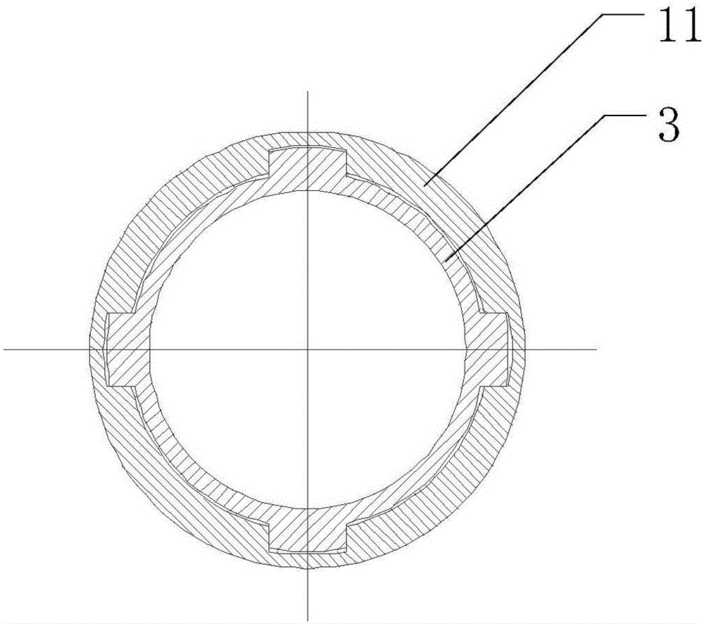
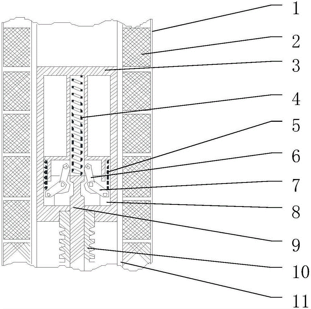
[0027] as attached figure 1 As shown, the floating reactor control rod driving mechanism of the present invention includes a pressure-bearing shell part, a driving motor part, a rod drop release mechanism part, a yoke coil part and a driving screw part. Among them: the pressure-bearing shell components are composed of the screw stroke shell 11, the motor pressure-bearing shell 17 and the guide sleeve 18, which together form the pressure boundary, wherein the motor pressure-bearing shell 17 and the reactor top cover (not shown in the figure) The connection is fixed; the driving motor components are composed of stator windings 15, rotor 14, nuts 13, thrust bearings 16 and radial bearings 12, wherein the stator windings 15 can be ins...


PUM


Abstract

The invention provides a control rod driving mechanism of a floating type reactor. The control rod driving mechanism of the floating type reactor comprises a pressure bearing shell part, a driving motor part, a rod dropping and releasing mechanism part, a magnet yoke coil part and a driving screw part. The control rod driving mechanism of the floating type reactor is reliable in driving action, high in operation accuracy, and simple and practical in structure; the power control and the reactor safety control function of the floating type reactor under various working conditions can be implemented.

Description

technical field [0001] The invention relates to a control rod driving mechanism of a nuclear power plant reactor, in particular to a control rod driving mechanism applied to a floating reactor. Background technique [0002] The nuclear reactor control rod drive mechanism is the most important control system and servo equipment of the safety protection system of the reactor. Because the working environment is different from land-based, the floating power plant reactor is in a state of periodic swing at all times. At this time, the driving mechanism cannot always maintain a fixed vertical state. Relying on gravity as the driving force for the control rods to insert into the core can no longer safely realize the rod dropping action. . When the floating stack tilts at a large angle, or even overturns, gravity becomes the resistance to the movement of the control rods, hindering its original set rod drop action. Therefore, the driving mechanism of the original land-based nuclea...

Claims


Application Information

Patent Timeline
IPC IPC(8): G21C7/14
CPCG21C7/14Y02E30/30
Inventor 白勇军刘刚史骁辰王丰林绍萱王德斌翁娜
Owner SHANGHAI NUCLEAR ENG RES & DESIGN INST CO LTD
Why Eureka
Try Eureka