

Battery housing and manufacturing method thereof, battery, battery bank, battery pack and electric vehicle
A technology for battery casings and battery packs, which is used in the manufacture of electric vehicles, battery pack components, and secondary batteries, can solve problems such as poor sealing and connection strength, and achieve high reliability, convenient automated production, and good connection strength. and sealing performance
- Summary
- Abstract
- Description
- Claims
- Application Information
AI Technical Summary
Problems solved by technology
Method used
Image

Examples
Embodiment 1
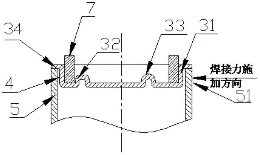
[0058] Such as figure 2 As shown, the cover plate of aluminum alloy is molded to have a sunken cover plate body, reinforcing ribs, straight lift positions of the cover plate and lap joints. Put the cover plate into the aluminum alloy shell, and the overlapping part overlaps the edge of the opening of the shell, and the part of the shell corresponding to the straight lift position of the cover plate is the straight lift position of the shell.
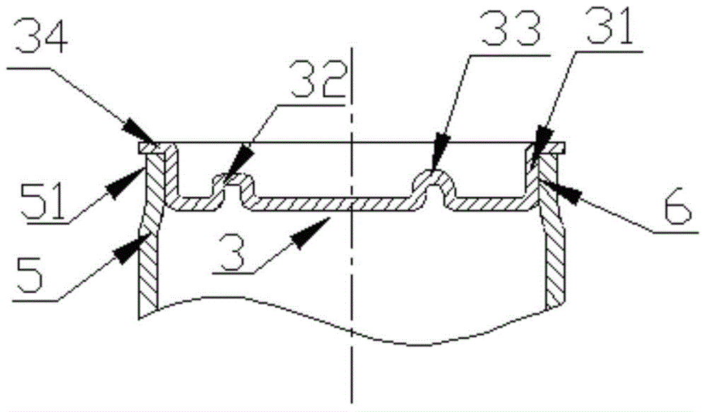
[0059] Place the vertical lifting position of the shell and the vertical lifting position of the cover plate in parallel and at intervals with a gap of 1.0mm, and then perform electromagnetic pulse welding (PS48-16 / 25 model of PST Company) at the place to be connected, and the welding energy is 30KJ, and the battery is obtained. housing, soldering locations such as figure 1 shown. Wherein, the width of the formed connecting region is 3 mm.
[0060] The casing of the obtained battery was tested for connection strength and sealing perf...
Embodiment 2
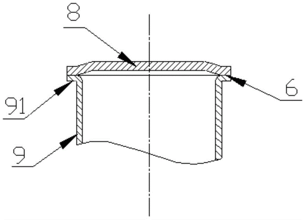
[0063] Such as Figure 4 As shown, the stainless steel housing is formed with bent edges.
[0064] Place the magnesium-aluminum alloy cover plate on the top of the flange, the angle between the flange and the cover plate is 5°, and the gap is 1.5mm, and then perform electromagnetic pulse welding (PS48-16 / 25 model of PST Company) at the place to be connected , the welding energy is 48KJ, to get the shell of the battery, the welding position is as follows image 3 shown. Wherein, the width of the formed connecting region is 5 mm.
[0065] The casing of the obtained battery was tested for connection strength and sealing performance, and the connection strength was 270 MPa, and the sealing strength was 1.05 MPa.
[0066] Use a metallographic microscope to observe the structure and morphology of the connection between the cover plate and the shell, such as Figure 6 As shown, there is no alloy phase diagram.
Embodiment 3
[0068] Such as figure 2 As shown, the stainless steel cover plate is formed to have a sinking cover plate body, reinforcement ribs, cover plate straight-up position and lap joints. Put the cover plate into the aluminum alloy shell, and the overlapping part overlaps the edge of the opening of the shell, and the part of the shell corresponding to the straight lift position of the cover plate is the straight lift position of the shell.
[0069] Place the vertical lifting position of the shell and the vertical lifting position of the cover plate in parallel and at intervals with a gap of 1.2mm, then perform electromagnetic pulse welding (PS48-16 / 25 model of PST Company) at the place to be connected, and the welding energy is 35KJ to obtain the battery. housing, soldering locations such as figure 1 shown. Wherein, the width of the formed connecting region is 5 mm.
[0070] The casing of the obtained battery was tested for connection strength and sealing performance, and the con...
PUM
| Property | Measurement | Unit |
|---|---|---|
| Connection strength | aaaaa | aaaaa |
| Connection strength | aaaaa | aaaaa |
| Connection strength | aaaaa | aaaaa |
Abstract
Description
Claims
Application Information