
Fireproof ventilation capacitance compensation cabinet

A capacitor compensation cabinet and cabinet technology, applied in the field of capacitor compensation cabinets, can solve problems such as affecting the service life of electrical components, reducing the service life of equipment, damaging voltage quality, etc., to enhance ventilation and heat dissipation, prolong service life, and have high safety. Effect

Inactive Publication Date: 2016-07-20
DONGMING POWER SUPPLY CO STATE GRID SHANDONG ELECTRIC POWER CO
View PDF4 Cites 14 Cited by
  • Summary
  • Abstract
  • Description
  • Claims
  • Application Information

AI Technical Summary

Problems solved by technology

[0002] Most of the load types in the power system are inductive loads, coupled with the widespread use of power electronic equipment by power companies, the power factor of the grid is low, and the low power factor reduces the utilization of equipment, increases power supply investment, and damages The voltage quality reduces the service life of the equipment and greatly increases the line loss. In order to improve the energy waste caused by the low power factor of the power grid and the unfavorable factors for power supply production, it is necessary to use a capacitor compensation cabinet to improve the power factor. However, due to the use of electrical equipment High frequency, easy to cause high temperature fire
In addition, the ventilation device of the existing capacitor compensation cabinet is a ventilation grid installed at the bottom of the capacitor compensation cabinet. The ventilation and heat dissipation effect of this ventilation grid is not good, which affects the service life of various electrical components in the capacitor compensation cabinet.

Method used


Image

  • Fireproof ventilation capacitance compensation cabinet
  • Fireproof ventilation capacitance compensation cabinet
  • Fireproof ventilation capacitance compensation cabinet

Examples


Embodiment Construction

[0021] The technical solutions of the present invention will be further described in detail below in conjunction with specific embodiments.

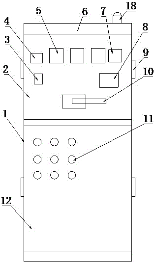
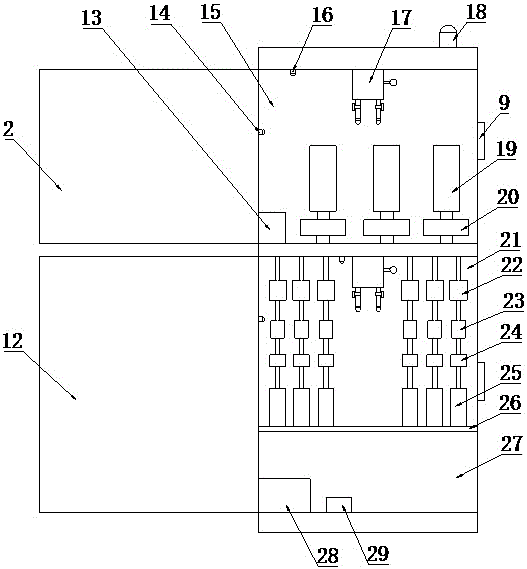
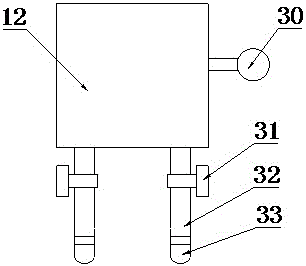
[0022] see Figure 1-4 , a fire-proof and ventilated capacitor compensation cabinet, comprising a cabinet body 1; the cabinet body 1 is divided into an upper cabinet body 15 and a lower cabinet body 21, and the front ends of the upper cabinet body 15 and the lower cabinet body 21 are correspondingly provided with upper cabinet doors 2 and the lower cabinet door 12, the upper cabinet door 2 is provided with a transfer switch 3, a reactive power meter 4, an ammeter 5, a power factor meter 7, a reactive power compensation controller 8 and a knife melting switch interface 10, the lower A plurality of indicator lights 11 are evenly spaced on the cabinet door 12 to indicate the working status of the capacitor compensation cabinet; in order to enhance the ventilation and heat dissipation effect of the cabinet body 1, a fan 9 is arranged on the ...


PUM


Abstract

The invention discloses a fireproof ventilation capacitance compensation cabinet, which comprises a cabinet body, wherein the interior of the cabinet body is divided into an upper cabinet body and a lower cabinet body, the front end of the upper cabinet body is provided with an upper cabinet door, and the front end of the lower cabinet body is provided with a lower cabinet door; the cabinet body is provided with a fan; a lightning arrester, knife-fuse switches and current transformers are arranged inside the upper cabinet door, the knife-fuse switches are arranged above the current transformers; miniature circuit breakers, AC contactors, thermal relays and AC capacitors are arranged inside the lower cabinet body; a temperature sensor, a smoke sensor and a fire extinguisher are arranged in each of the upper cabinet door and the lower cabinet body; each fire extinguisher is provided with a spray pipe, the tail end of each spray pipe is provided with a sprayer, and each sprayer is provided with an electromagnetic valve; a controller is arranged inside the cabinet body, and the temperature sensors, the smoke sensors and the electromagnetic valves are electrically connected with the controller; and a storage battery is arranged inside the cabinet body, and the storage battery is electrically connected with the controller. The fireproof ventilation capacitance compensation cabinet has good ventilation and heat dissipation effects, can extinguish fire in the bud, and is high in safety.

Description

technical field [0001] The invention relates to the technical field of electrical equipment, in particular to a fireproof and ventilated capacitance compensation cabinet. Background technique [0002] Most of the load types in the power system are inductive loads, coupled with the widespread use of power electronic equipment by power companies, the power factor of the grid is low, and the low power factor reduces the utilization of equipment, increases power supply investment, and damages The voltage quality reduces the service life of the equipment and greatly increases the line loss. In order to improve the energy waste caused by the low power factor of the power grid and the unfavorable factors for power supply production, it is necessary to use a capacitor compensation cabinet to improve the power factor. However, due to the use of electrical equipment The frequency is high, and it is easy to cause high temperature and fire. In addition, the ventilation device of the ex...

Claims


Application Information

Patent Timeline
IPC IPC(8): H02J3/18H02B1/56H02B1/28
CPCY02E40/30H02J3/18H02B1/28H02B1/565
Inventor 王艳萍
Owner DONGMING POWER SUPPLY CO STATE GRID SHANDONG ELECTRIC POWER CO
Learn More