
Polarizing film, polarizing film with adhesive layer, and image display device

A technology of adhesive layer and polarizing film, which is applied in the direction of polarizing elements, layered products, optics, etc., can solve the problems of low moisture permeability, insufficient adhesion between adhesive layer and polarizing film, etc. The effect of small amount of penetration and small damage

Active Publication Date: 2016-07-20
NITTO DENKO CORP
View PDF14 Cites 0 Cited by
  • Summary
  • Abstract
  • Description
  • Claims
  • Application Information

AI Technical Summary

Problems solved by technology

In addition, when a polarizing film using a transparent protective film with low moisture permeability is used as a polarizing film with an adhesive layer, the adhesiveness between the adhesive layer and the polarizing film is insufficient.

Method used


Image

  • Polarizing film, polarizing film with adhesive layer, and image display device
  • Polarizing film, polarizing film with adhesive layer, and image display device
  • Polarizing film, polarizing film with adhesive layer, and image display device

Examples


Embodiment 1

[0172]

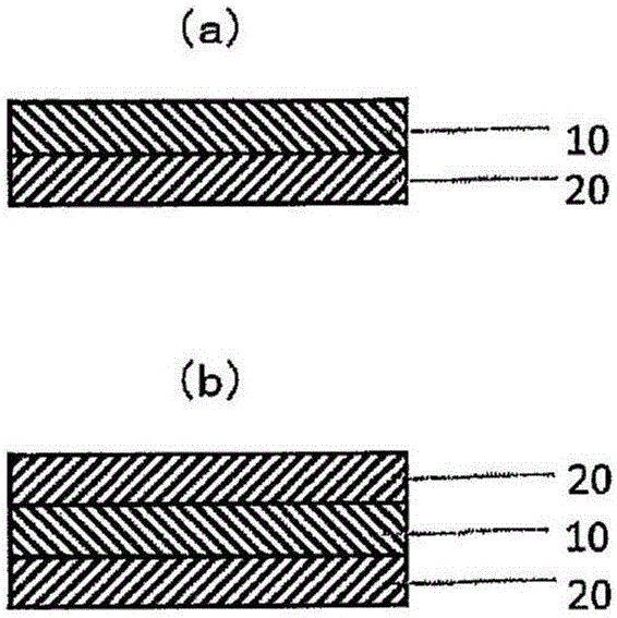
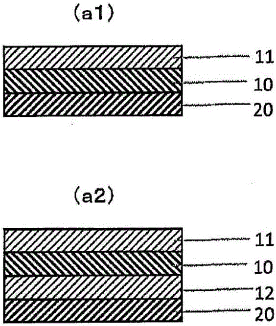
[0173] Silicon oxide was vapor-deposited on the polarizer (polarizing film) surface of the thin polarizing film (A1) by sputtering to form an inorganic layer (B1) with a thickness of 100 nm to obtain a polarizing film with an inorganic layer.

Embodiment 2~8

[0175] In of Example 1, except having changed the formation material and / or thickness of an inorganic layer as shown in Table 1, it carried out similarly to Example 1, and obtained the polarizing film with an inorganic layer.

Embodiment 9~12

[0177] In of Example 1, except having used the film shown in Table 1 instead of the said thin polarizing film (A1), it carried out similarly to Example 1, and obtained the polarizing film with an inorganic layer.


PUM


Abstract

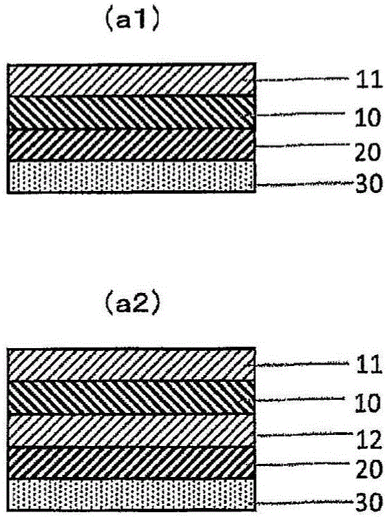
This polarizing film is characterized by comprising an inorganic layer on one or both surfaces of a polarizing element. The polarizing film has barrier properties against steam, and, even when used in the mode of a polarizing film with an adhesive layer, has good adhesion with the adhesive layer.

Description

technical field [0001] The present invention relates to polarizing films having inorganic layers. This polarizing film can be used as a polarizing film with an adhesive layer which has an adhesive layer. Further, the present invention relates to a liquid crystal display device using the above-mentioned polarizing film or the above-mentioned polarizing film with an adhesive layer, a display device (organic EL display device) having an organic electroluminescent element, and an image display device such as a PDP. Background technique [0002] In a liquid crystal display device or the like, it is essential to arrange polarizing elements on both sides of a liquid crystal cell because of an image forming method, and generally a polarizing film is bonded. When bonding the above-mentioned polarizing film to a liquid crystal cell, an adhesive is usually used. Moreover, in bonding a polarizing film and a liquid crystal cell, in order to reduce light loss normally, each material is ...

Claims


Application Information

Patent Timeline
Patent Type & Authority Applications(China)
IPC IPC(8): G02B5/30
CPCG02B5/3033G02B1/18B32B7/12G02B5/3083
Inventor 保井淳外山雄祐伊崎章典藤野望
Owner NITTO DENKO CORP
Learn More