Driven decoupling mechanism aimed at rope kinematic coupling and decoupling method thereof

A kinematic coupling and rope technology, applied in the field of robotic arm systems, achieves the effects of wide application range, simplified motion control algorithm, and low friction

Active Publication Date: 2016-07-27
南京若希自动化科技有限公司
View PDF7 Cites 3 Cited by
  • Summary
  • Abstract
  • Description
  • Claims
  • Application Information

AI Technical Summary

Problems solved by technology

[0004] In order to solve the kinematic coupling problem of the rope driven by the series rope drive mechanical system, the present invention provides a passive decoupling mechanism and decoupling method for the kinematic coupling of the rope, which is simple, reliable and easy to implement

Method used


Image

  • Driven decoupling mechanism aimed at rope kinematic coupling and decoupling method thereof
  • Driven decoupling mechanism aimed at rope kinematic coupling and decoupling method thereof
  • Driven decoupling mechanism aimed at rope kinematic coupling and decoupling method thereof

Examples


Embodiment Construction

[0028] The accompanying drawings disclose non-restrictive structural schematic diagrams of the present invention involved and preferred implementations, and the technical solution of the present invention will be described in detail below in conjunction with the accompanying drawings.

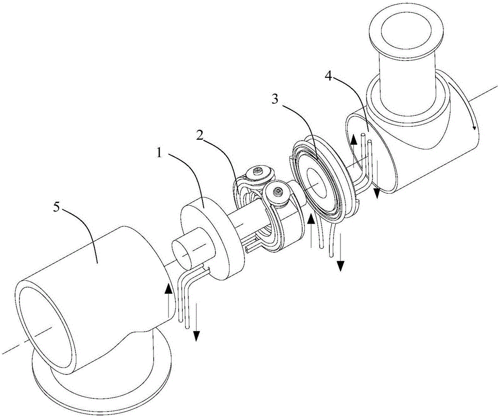
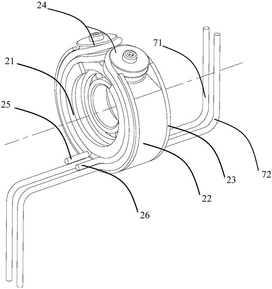
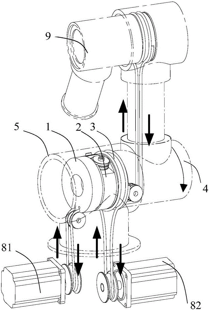
[0029] see figure 1 , 2 As shown, a mechanism for passively decoupling the motion of the driving rope for the rope-driven tandem manipulator is provided. From front to back, it includes joint base 5, fixed wheel 1, follower wheel 2, driving wheel 3, and current joint connecting rod 4. Wherein the fixed wheel 1 includes a fixed wheel disc and a fixed wheel axle, and is fixedly connected with the joint base 5 and cannot rotate; the follower wheel 2 and the driving wheel 3 are all mounted on the fixed wheel axle through bearings to be rotatable, but the axial movement is all blocked. Restriction; driving wheel 3 is fixedly connected with current joint link 4. The mechanism also includes a left ...


PUM


Abstract

The invention discloses a driven decoupling mechanism aimed at rope kinematic coupling and a decoupling method thereof, and relates to a multi-joint rope-driven tandem mechanical arm system. The mechanism comprises a fixed wheel, a follower wheel, a driving wheel, a guide pulley and uncoupling ropes, wherein the driving wheel is connected with a joint connecting rod; the fixed wheel is connected with a joint base; the follower wheel is driven through utilizing the forward and reverse winding of the uncoupling ropes, so that the motion speed of the follower wheel is one second the rotation speed of the joint connecting rod; a driving rope of a joint at the back end is wound in the forward and reverse directions of rope guide grooves in the follower wheel, so that the displacement change of the driving rope caused by rotation of the joint connecting rod and the displacement change caused by rotation of the follower wheel counteract with each other; the driving rope passing through the uncoupling mechanism and the joint connecting rod do not have relative displacement, so that the kinematic uncoupling of the rope is achieved; the uncoupling mechanism can work in the temperature of 0 to 300 DEG C, the working range is wide, and the structure is simple, compact and reliable; and the rope kinematic uncoupling mechanism and the rope driving joint are mounted in a matching manner, so that the modularization can be achieved, and the application range is wide.

Description

technical field [0001] The invention relates to a passive decoupling mechanism for rope kinematic coupling and a decoupling method thereof, in particular to a multi-joint rope-driven manipulator system for serial kinematic coupling. Background technique [0002] At present, the widely used robotic arm has large volume and mass, complex structure, high rigidity, low load-to-weight ratio, high energy consumption and low efficiency for grabbing loads. In order to reduce the weight and moment of inertia of the manipulator, many researchers have applied the rope drive technology to the tandem manipulator in recent years. [0003] Rope-actuated technology uses cables to transmit motion and force. It installs all the drive units on the base, transmits motion and force remotely through the rope, and realizes the motion of the joint. Because the drive unit is external and the rope transmission is used, the mass and volume of the robotic arm can be greatly reduced, but at the same t...

Claims


Application Information

Patent Timeline
Patent Type & Authority Applications(China)
IPC IPC(8): B25J9/10B25J17/02
CPCB25J9/104B25J9/1045B25J17/025
Inventor 陈柏印亮华达人白东明徐伟张磊吴志恒蒋素荣席万强
Owner 南京若希自动化科技有限公司
Why Eureka
Try Eureka