Secondary quasi-zero dynamic stiffness suspension and bogie for low-floor trams
A tram and suspension device technology, applied in the field of secondary springs, can solve the problems of poor low-frequency vibration isolation, poor running comfort, and reduced load-carrying capacity, and achieve the advantages of small space occupation, low cost, and good vibration isolation characteristics Effect
- Summary
- Abstract
- Description
- Claims
- Application Information
AI Technical Summary
Problems solved by technology
Method used
Image
Examples
Embodiment 1
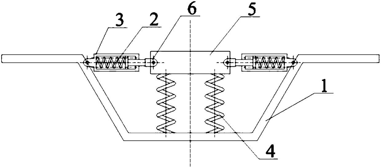
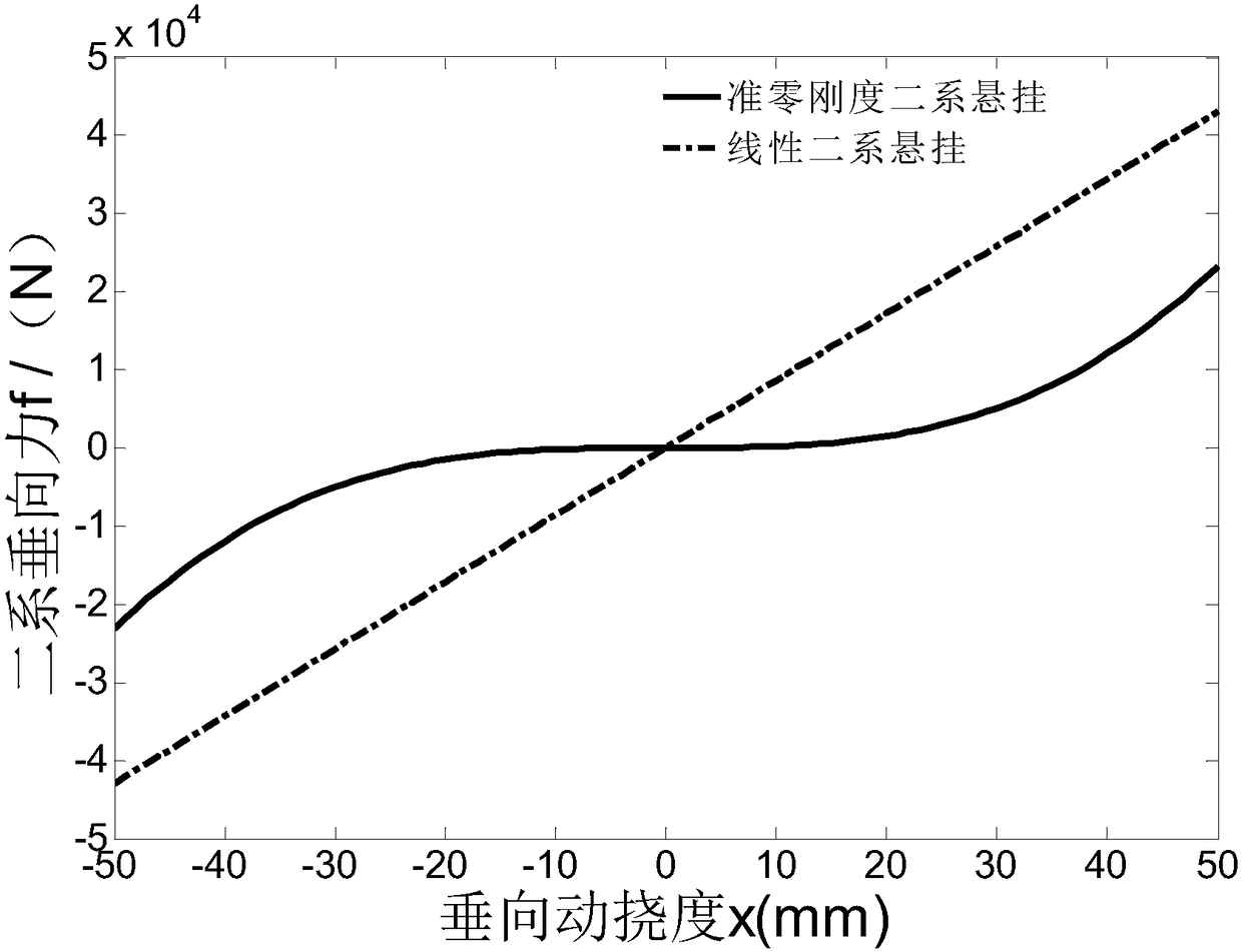
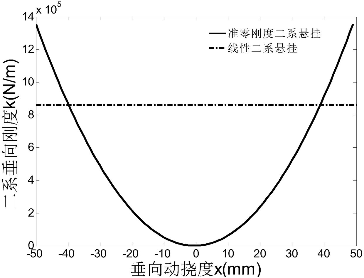
[0028] Such as figure 1 As shown, a secondary quasi-zero dynamic stiffness suspension device for low-floor trams is installed between the car body and the bogie body, including a transverse spring 2, two vertical springs 4 and a The car body connecting piece 5, one end of the transverse spring 2 and one end of the vertical spring 4 are respectively connected with the bar-shaped car body connecting piece 5, the other end of the transverse spring 2 and the other end of the vertical spring 4 are connected with the bogie body respectively, and the transverse spring 2. There are at least two, and they are all in a pre-compressed state. After the two transverse springs 2 are combined, the forces generated in the transverse direction cancel each other out, and the differential of the vertical force to the displacement, that is, the vertical stiffness is a negative stiffness; after being connected in parallel with the vertical spring 4, the entire secondary suspension device has high ...
Embodiment 2
[0037] The difference from Example 1 is that the number of transverse springs 2 and vertical springs 4 can be increased, for example, two pairs of transverse springs 2 and three pairs of vertical springs 4 can be set to reduce the stress on a single spring and prolong the service life .
Embodiment 3
[0039] The suspension device described in embodiment 1 or 2 is applied to the tram bogie, such as figure 1 As shown, during installation, one end of the transverse spring 2 is rotationally connected to the side wall of the U-shaped side beam 1 of the bogie body through a connecting piece or directly, and the vertical spring 4 is fixedly connected to the bottom of the U-shaped side beam 1 of the bogie body , the car body connector 5 is connected with the car body. During installation, there is no need to modify the bogie body.
PUM
 Abstract
Description
Claims
Application Information
 - R&D
- Intellectual Property
- Life Sciences
- Materials
- Tech Scout
- Unparalleled Data Quality
- Higher Quality Content
- 60% Fewer Hallucinations
Browse by: Latest US Patents, China's latest patents, Technical Efficacy Thesaurus, Application Domain, Technology Topic, Popular Technical Reports.
© 2025 PatSnap. All rights reserved.Legal|Privacy policy|Modern Slavery Act Transparency Statement|Sitemap|About US| Contact US: help@patsnap.com


