Slot type concentrated solar Sterling power generation system

A trough solar and power generation system technology, applied in the field of solar free piston Stirling power generation system, can solve the problems of large initial investment, long construction period, complex structure, etc., and achieve a short construction period, flexible construction and environment-friendly. Effect

Inactive Publication Date: 2016-07-27
TECHNICAL INST OF PHYSICS & CHEMISTRY - CHINESE ACAD OF SCI
View PDF5 Cites 5 Cited by
  • Summary
  • Abstract
  • Description
  • Claims
  • Application Information

AI Technical Summary

Problems solved by technology

[0006] The technical problem to be solved by the present invention is to provide a trough-type concentrating solar Stirling power generation system, which is composed of a trough-type solar collector with relatively high market maturity and a free-piston Stirling generator. It solves the problems of complex structure, large initial investment and long construction period of the existing solar thermal power generation system

Method used


Image

  • Slot type concentrated solar Sterling power generation system
  • Slot type concentrated solar Sterling power generation system

Examples


Embodiment 1

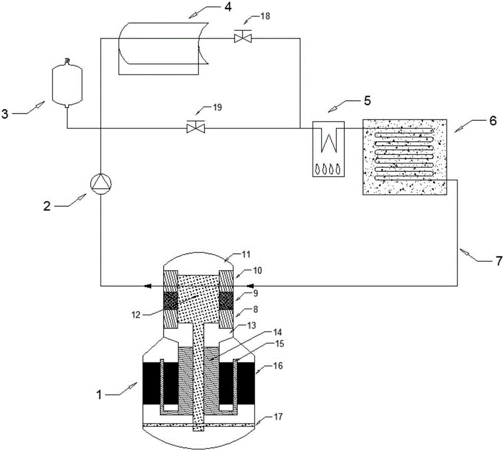
[0030] Such as figure 1 As shown, a trough-type concentrating solar Stirling power generation system provided in this embodiment includes a trough-type solar collector 4, a circulation pump 2 and a free-piston Stirling generator 1, and a thermal fluid delivery pipeline 7 for Connecting all components in the system, the trough solar collector 4, the circulation pump 2 and the free piston Stirling generator 1 are connected in sequence through the thermal fluid delivery pipeline 7 to form a power generation circuit.

[0031] The trough solar collector 4 adopted in this embodiment can effectively reduce the system cost and increase the reliability of the system at the same time. The trough solar collector 4 heats the heat transfer fluid inside it by reflecting sunlight, so that the heat transfer fluid The operating temperature is between 350-400°C; the circulation pump 2 is set on the heat fluid pipeline 7, and the appropriate model can be selected according to the heat transfer f...

Embodiment 2

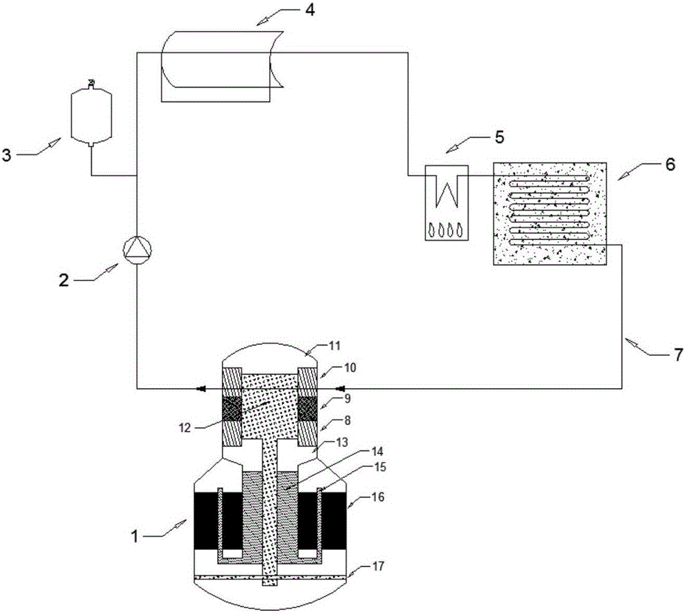
[0043] Such as figure 2 As shown, a trough-type concentrating solar Stirling power generation system provided by this embodiment has the same principle as that of Embodiment 1, and its structure is similar to that of Embodiment 1. The only difference is that in this embodiment, the post-combustion device 5 The inlet is only connected to the fluid outlet of the trough solar collector 4 , that is, the inlet of the afterburning device 5 is not connected to the thermal fluid pipeline 7 for communicating with the fluid outlet of the circulation pump 2 . And in this embodiment, no valve is set in the thermal fluid pipeline 7 between the inlet of the afterburning device 5 and the fluid outlet of the trough solar collector 4 .

[0044] The setting of this structure makes the system of this embodiment when the sunlight is sufficient during the day, the trough solar collector 4 provides thermal energy for the whole system, and the thermal storage device 6 is used to store the excess he...


PUM


Abstract

The invention relates to the technical field of solar thermal power generation, in particular to a slot type concentrated solar Sterling power generation system. The system comprises a slot type solar thermal collector, a circulating pump and a free-piston Sterling generator, wherein the slot type solar thermal collector, the circulating pump and the free-piston Sterling generator communicate in sequence via a hot fluid delivery pipeline; the slot type solar thermal collector heats a heat transfer fluid therein by reflecting sunlight; the circulating pump drives the heat transfer fluid to circularly flow in a power generation loop; and the free-piston Sterling generator converts heat energy transferred by the heated heat transfer fluid into electric energy. The slot type concentrated solar Sterling power generation system is formed by combination of the slot type solar thermal collector and the free-piston Sterling generator which are relatively high in market maturity currently, and solves the problems that existing solar thermal power generation systems are complex in structure, large in initial investment and long in construction cycle.

Description

technical field [0001] The invention relates to the technical field of solar thermal power generation, in particular to a solar Stirling power generation system, and more particularly to a distributed trough-type concentrating solar free-piston Stirling power generation system. Background technique [0002] With the large-scale application of fossil energy, the impact of energy shortage and environmental pollution on human economic and social development is becoming more and more obvious. my country is one of the regions with the most abundant solar energy resources in the world. Making full and reasonable use of solar energy resources is of great significance for reducing and eventually replacing the use of traditional energy sources. [0003] Solar power generation technologies mainly include photovoltaic power generation and photothermal power generation. Among them, photovoltaic power generation technology has achieved rapid development in the 21st century, but there ar...

Claims


Application Information

Patent Timeline
Patent Type & Authority Applications(China)
IPC IPC(8): F03G6/06F02G1/043F02G1/055
CPCY02E10/46F03G6/068F02G1/0435F02G1/055F02G2254/10F02G2254/30F02G2254/40
Inventor 吴张华李潜葛罗二仓余国瑶戴巍
Owner TECHNICAL INST OF PHYSICS & CHEMISTRY - CHINESE ACAD OF SCI
Why Eureka
Try Eureka