Breathing valve, oil tank cover and oil tank

A breathing valve and fuel tank cap technology, applied in the field of breathing valves, can solve problems such as polluting the air and the environment, polluting the air, and affecting health, and achieve the effect of preventing rupture and damage and ensuring normal fuel supply

Active Publication Date: 2016-07-27
CHONGQING BAIKE DINGYU TECH CO LTD
View PDF5 Cites 8 Cited by
  • Summary
  • Abstract
  • Description
  • Claims
  • Application Information

AI Technical Summary

Problems solved by technology

But the result is unsatisfactory, a large amount of volatile gas is directly discharged into the atmosphere to pollute the air
Especially when the engine is shaken, tilted, or even turned upside down, a large amount of oil and gas will overflow, which will seriously pollute the air and environment, affect people's health, and even cause safety hazards such as spontaneous combustion.

Method used


Image

  • Breathing valve, oil tank cover and oil tank
  • Breathing valve, oil tank cover and oil tank
  • Breathing valve, oil tank cover and oil tank

Examples


Embodiment 1

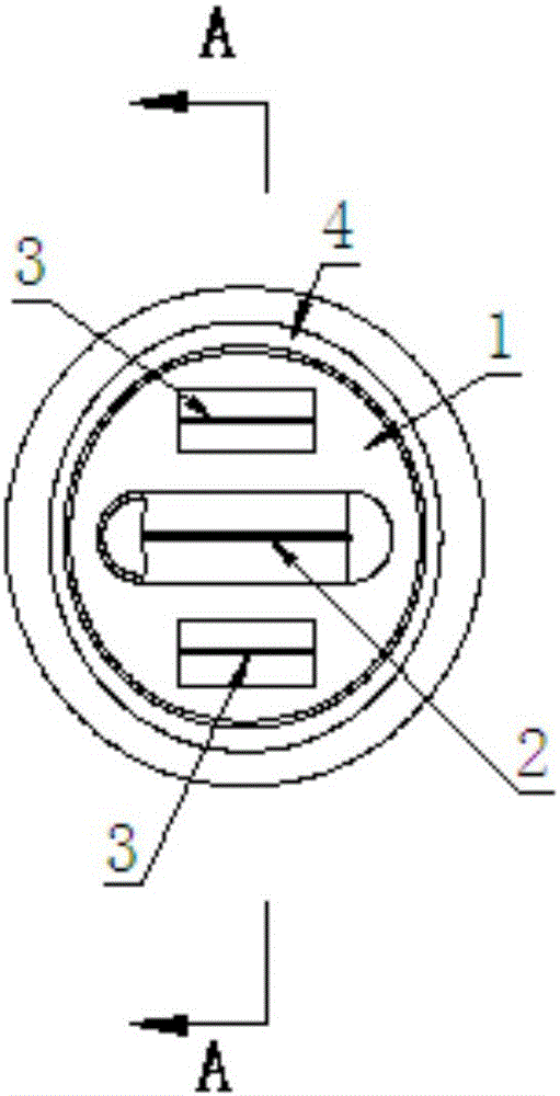
[0045] like Figure 1 to Figure 5 As shown, a breathing valve for a fuel tank cap includes a valve body 1 made of elastic material. Starting from 4, the elastic material mentioned here generally refers to rubber material.

[0046] A protruding part 5 for air intake is arranged on one side of the valve body 1, and one side here refers to the side facing the fuel tank after the breather valve is assembled.

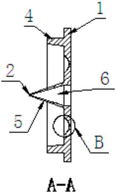
[0047] The protruding part 5 is wedge-shaped, and the protruding part 5 is integrated with the valve body 1 . The protruding part 5 has a cavity 6, and the valve body 1 is provided with a through hole that runs through both ends of the valve body, and the through hole communicates the cavity 6 with the outside atmosphere; When the pressure on one side of the protruding part 5 is lower than the pressure on the other side of the valve body 1, the slit will open; otherwise, the side wall of the wedge-shaped slit 2 can be squeezed and deformed and bonded under the action of th...

Embodiment 2

[0051] like Figure 6 to Figure 8 As shown, the structure and principle of the breathing valve of Embodiment 1 are the same, the difference lies in the position of the assembly protrusion 4 . In actual use, the position of the assembly protrusion 4 can be flexibly arranged and set according to requirements.

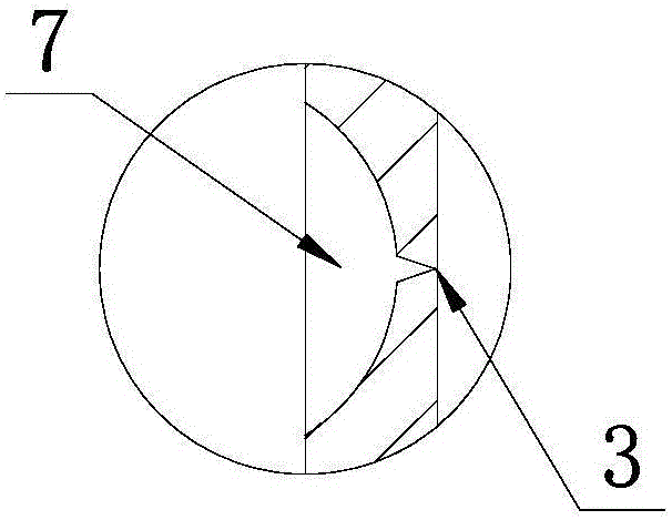
[0052]The fuel tank cap installed with the above-mentioned breather valve can ensure the airtightness of the fuel tank when it is installed on the fuel tank for use, and when the internal and external air pressure of the fuel tank is balanced, the gas volatilized by the fuel in the fuel tank will not be discharged into the atmosphere to pollute the air. When the engine vibrates greatly or works on bumpy road conditions, when the fuel tank is tilted or even inverted, the notch 2 and the slit 3 are all closed to prevent oil leakage. Even if the fuel tank is tilted or turned upside down for a long time, the air pressure in the fuel tank will increase and the cutting seam 3 ...


PUM


Abstract

The invention relates to a breathing valve, an oil tank cover and an oil tank. The breathing valve for the oil tank cover comprises a valve body. A one-way air inlet part and a one-way exhaust part are arranged on the valve body. When the pressure in the oil tank and outside pressure are balanced, the oil tank is closed, volatile gas in the oil tank cannot be exhausted out, and the environment is protected. When negative pressure is formed in the oil tank, outside air is led into the oil tank through the one-way air inlet part, and balance of the air pressure of the oil tank is ensured. When the pressure in the oil tank is increased, gas in the oil tank is exhausted to the outside through the one-way exhaust part, when the oil tank is inclined or inverted, it is ensured that oil in the oil tank cannot flow out through the breathing valve, and therefore the use safety of the oil tank is ensured.

Description

technical field [0001] The invention relates to a breathing valve, in particular to a breathing valve for maintaining air pressure balance which can be used on fuel tank caps, medical equipment, petrochemical equipment and the like. Background technique [0002] At present, many devices are equipped with pressure relief valves in order to maintain internal air pressure balance. Such as fuel tank etc., the fuel tank cover of existing gasoline, diesel engine fuel tank all adopts carbon powder and adsorption sponge to stop gasoline diesel oil from volatilizing and overflowing. But the result is unsatisfactory, and a large amount of volatile gases are directly discharged into the atmospheric environment to pollute the air. Especially when the engine is shaken, tilted, or even turned upside down during operation, a large amount of oil and gas will overflow, seriously pollute the air and the environment, affect people's health, and even cause safety hazards such as spontaneous co...

Claims


Application Information

Patent Timeline
Patent Type & Authority Applications(China)
IPC IPC(8): F16K17/02
CPCF16K17/02B60K2015/03547B60K15/03519B60K15/0406F16K15/147F16K17/19B60K15/035B65D51/165
Inventor 张毅
Owner CHONGQING BAIKE DINGYU TECH CO LTD
Why Eureka
Try Eureka