Smoke gathering device used for electric arc furnace and refining furnace and smoke gathering method

A technology for refining furnaces and electric arc furnaces, which is applied in soot collection devices, fixed soot collection closed rooms, and soot collection fields. The effect of high degree of automation and simple operation

Active Publication Date: 2016-07-27
尼欧迪克(青岛)环保科技有限公司
View PDF5 Cites 1 Cited by
  • Summary
  • Abstract
  • Description
  • Claims
  • Application Information

AI Technical Summary

Problems solved by technology

[0007] However, this structure has a great disadvantage: when the smoke rises from the furnace to the top suction hood, on the one hand, it will diffuse and spread into the workshop.
On the other hand, the smoke and dust will be blown away by the cross wind in the workshop, and it is difficult for the top suction hood to capture
These scattered fumes seriously pollute the workshop and the surrounding environment. Because this type of cover is not sealed, the noise is very loud, which endangers the health of operators.
In addition, there is an active connection between the mobile cover and the air duct, and frequent movement will cause failure at the joint, which will directly affect the dust removal effect

Method used


Image

  • Smoke gathering device used for electric arc furnace and refining furnace and smoke gathering method

Examples


Embodiment 1

[0039] Take electric arc furnace as an example

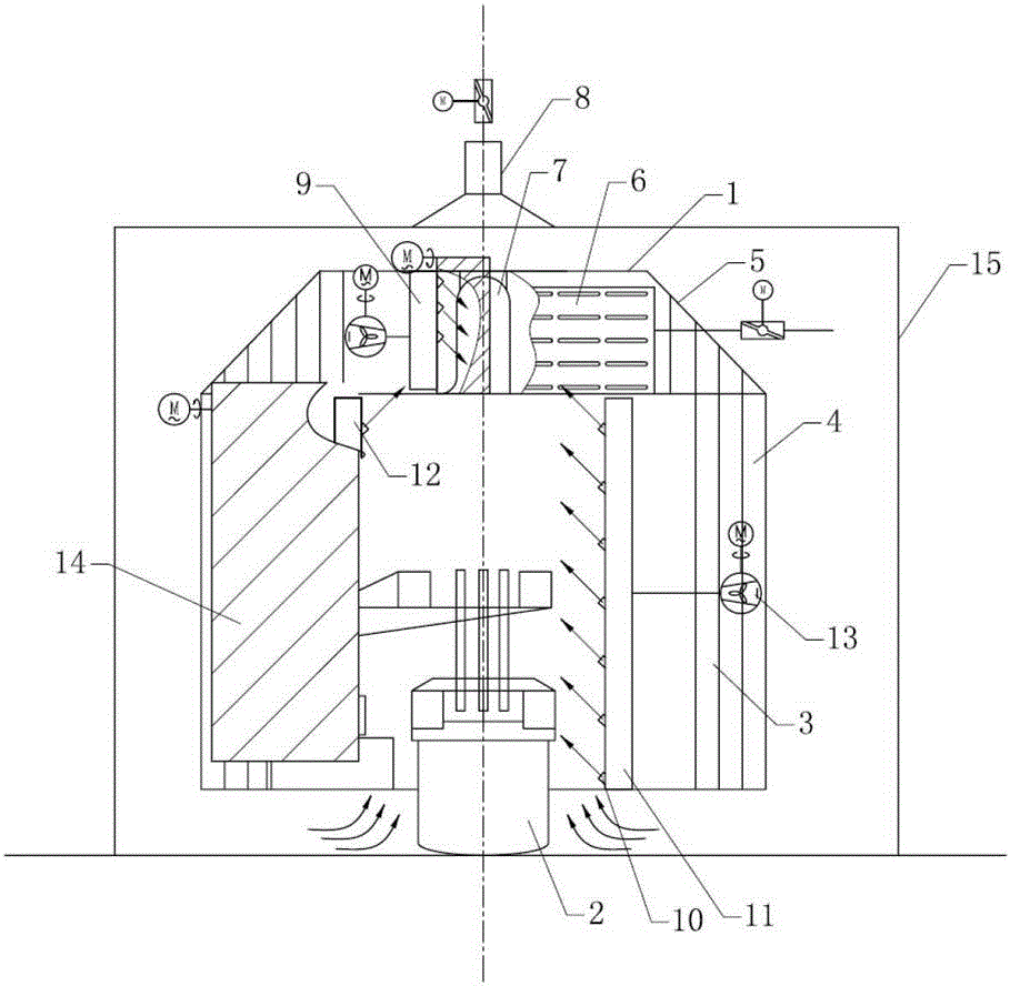
[0040] Such as figure 1As shown, a dust collection device for electric arc furnaces and refining furnaces includes a sealed chamber 1 that seals and surrounds an electric arc furnace 2, and the sealed chamber 1 includes a steel structure frame 3 that plays a supporting role , the steel structure frame 3 is fixedly installed, and the sound-absorbing and heat-insulating layer 4 is installed on the steel structure frame 3 as a wallboard, thereby forming the sealed chamber 1 with high airtightness. The outermost layer of the sound-absorbing and heat-insulating layer 4 is a 1mm color steel plate, then a layer of 2mm galvanized sheet, and then a layer of 100mm aluminum silicate that can withstand high temperatures of 600°C, and the inner layer is a layer of 1.5mm high temperature resistant glass fiber Cloth, the innermost layer is a layer of 1.5mm stainless steel perforated plate. The stainless steel perforated plate can effectively...

Embodiment 2

[0048] Taking the refining furnace as an example, the structure is basically the same as that of Embodiment 1, so no illustration is given.

[0049] The difference from Embodiment 1 is that the sealed chamber seals and surrounds the refining furnace. In addition, the air curtain adopts the following structure: the opening is provided with a flat air outlet, and there are several flat air outlets, which are all connected to the air duct, and the opening side of the top of the closed chamber 1 is provided with a first air duct , the angle between the flat air outlet arranged on the first air duct and the horizontal direction is 16°, and the blowing direction is downward and towards the inside of the closed chamber, and the two sides of the opening at the front of the closed chamber are respectively set There are a second air duct and a third air duct, the angle between the flat air outlet of the second air duct and the third air duct and the horizontal direction is 8°, and the b...


PUM


Abstract

The invention discloses a smoke gathering device used for an electric arc furnace and a refining furnace. The smoke gathering device comprises a sealing chamber, the sealing chamber seals and surrounds equipment generating smoke, an opening is formed in the sealing chamber, and is provided with a sealing door, the sealing door achieves opening and closing, and therefore the opening is opened and sealed; and the opening forms an air curtain; and a dust suction cover is arranged on the top of the sealing chamber, and the dust suction cover is used for gathering the smoke. Meanwhile, the invention discloses a smoke gathering method achieved through the smoke gathering device used for the electric arc furnace and the refining furnace. The device and method are high in smoke gathering rate, low in noise, easy to operate, safe, reliable and high in automation degree.

Description

technical field [0001] The invention relates to the technical field of dedusting equipment, in particular to a soot collection device for electric arc furnaces and refining furnaces, especially a fixed soot collection closed chamber suitable for dust removal in electric arc furnace refining furnaces, and the soot collection device realized by the device. capture method. Background technique [0002] At present, China's mainstream electric furnace dust removal generally adopts a combination of a mobile airtight cover and a top suction hood. The ceiling suction hood is set on the roof of the factory building. The airtight cover is mainly composed of two parts: a fixed cover body and a mobile cover body. The back of the furnace and both sides of the furnace are fixed covers, and the operating side in front of the furnace is a movable cover. [0003] Under the working conditions of normal smelting after the electric arc furnace is charged, the top suction hood on the roof doe...

Claims


Application Information

Patent Timeline
Patent Type & Authority Applications(China)
IPC IPC(8): F27D17/00
CPCF27D17/001F27D17/002F27D17/003
Inventor 马卫东苏强黄文强李永铸
Owner 尼欧迪克(青岛)环保科技有限公司
Why Eureka
Try Eureka