A cross-axis image measurement method for three-dimensional motion analysis of glass pipelines

A three-dimensional motion and image measurement technology, applied in measurement devices, photogrammetry/video measurement, surveying and navigation, etc., can solve problems such as tracking failure, motion damping, and inability to extract marker points, and improve accuracy and precision. , the effect of promoting application and reducing errors

Inactive Publication Date: 2018-04-10
DALIAN UNIV OF TECH
View PDF2 Cites 0 Cited by
  • Summary
  • Abstract
  • Description
  • Claims
  • Application Information

AI Technical Summary

Problems solved by technology

However, for the transparent glass pipelines used in ocean engineering experiments, their own texture features cannot be used, and the method of pasting active or passive luminescent markers on the surface is only to track the movement of a certain point on the outer wall of the pipeline. In addition to translational motion, when there is rotational motion, it will not be possible to characterize the motion of the axis of the pipeline at this position (the diameter of the glass tube in the experiment cannot be ignored relative to the length of the tube)
In addition, when the pipeline rotates at a large angle, the marking points pasted on one side cannot be extracted due to occlusion, resulting in tracking failure, and the pasted markers cannot be completely attached due to long-term immersion in water during underwater experiments. Combine the pipeline to form motion damping
[0008] To sum up, there is currently no glass pipeline movement measurement technology based on the principle of stereo vision that can well solve the problem of measuring the movement of transparent glass pipelines in experimental tanks.

Method used


Image

  • A cross-axis image measurement method for three-dimensional motion analysis of glass pipelines

Examples


Embodiment Construction

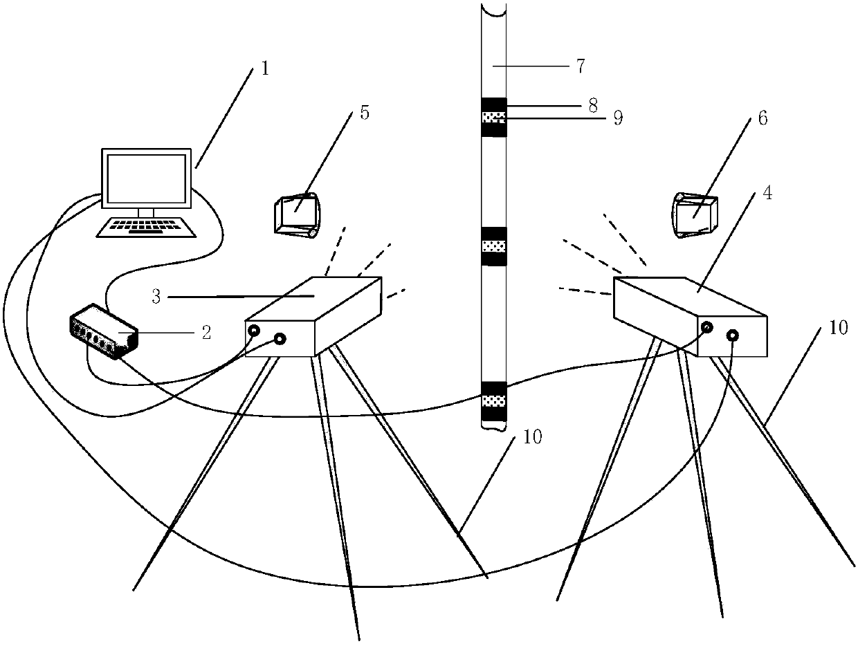
[0023] The device that method of the present invention adopts, its structural representation is as attached figure 1 Shown:

[0024] The cross-axis image measurement system for three-dimensional motion analysis of glass pipelines includes a computer 1, a synchronous controller 2, two high-speed industrial cameras (camera 3 and camera 4), two LED supplementary lights (complementary light 5 and Fill light 6), glass pipeline 7, black spraying stripes 8, yellow fluorescent stripes 9, tripod 10. The camera 3 and the camera 4 are fixed on the tripod 10, arranged on both sides of the pipeline axis (arranged across the axis) and at a certain angle to each other to observe the target pipeline 7, and connected to the computer 1 through a transmission wire. The control port of the synchronous controller 2 is connected with the computer 1, and the synchronous signal output port is connected with two cameras, and is responsible for the synchronous acquisition control of images. And two L...


PUM


Abstract

The invention belongs to the technical field of image measuring and discloses a cross axis type image measuring method for glass pipeline three-dimensional kinematic analysis.Two vidicons are fixed to a tripod and arranged on the two sides of a pipeline axis, an angle is formed by the two vidicons so that a target pipeline can be observed, and the two vidicons are connected with a computer through transmission wires.A control port of a synchronous controller is connected with the computer, synchronous signal output ports of the synchronous controller are connected with the two vidicons, and the synchronous controller is in charge of image synchronous collection control.Two LED light-compensating lamps are arranged on the two sides of the vidicons and used for illuminating the pipeline to be measured.Before measuring, firstly, narrow-band yellow waterproof fluorescent paint is sprayed to the measuring position around the circumference of the glass pipeline, and then narrow-band black waterproof paint is sprayed to the two sides of the narrow-band yellow waterproof fluorescent paint.The physical offset problem of the center of a pipeline image at different time points during glass pipeline kinematic measuring, the strong light reflection effect of glass and the problem that homonymy points on the surface of the pipeline are difficult to retrieve in the kinematic process are taken into full consideration.

Description

technical field [0001] The invention belongs to the technical field of image measurement, relates to the problem of three-dimensional motion measurement of cylindrical transparent pipelines, and in particular relates to a pipeline positioning and tracking method based on binocular vision. Background technique [0002] In offshore engineering pipeline model experiments, cylindrical glass pipelines are often used instead of actual pipelines for motion analysis, such as vortex-induced vibration research and shape change research of oil production pipelines. Therefore, a high-precision glass pipeline motion tracking measurement method is very important for the experimental research of the pipeline. At present, the motion measurement of the pipeline can be carried out by contact measurement method or non-contact measurement method, the former such as accelerometer measurement method, strain indirect measurement method, etc.; the latter such as Doppler laser visual measurement, e...

Claims


Application Information

Patent Timeline
Patent Type & Authority Patents(China)
IPC IPC(8): G01C11/00
CPCG01C11/00
Inventor 杜海孟娟李木国
Owner DALIAN UNIV OF TECH
Why Eureka
Try Eureka