
Central temperature estimation method of crossed temperature measurement device of blast furnace

A technology of cross temperature measurement and center temperature, which is applied to blast furnaces, inspection devices, blast furnace details, etc., can solve the problems of easy damage of temperature point sensors, long replacement cycle, and inability to continuously measure temperature

Active Publication Date: 2016-07-27
NORTHEASTERN UNIV
View PDF1 Cites 8 Cited by
  • Summary
  • Abstract
  • Description
  • Claims
  • Application Information

AI Technical Summary

Problems solved by technology

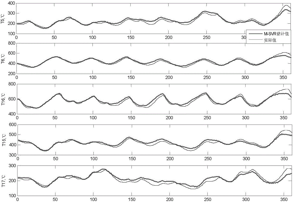
[0003] In order to solve the problem that the temperature point sensor in the center of the cross temperature measuring device is easily damaged, the replacement period is long, and the temperature cannot be continuously measured, the present invention is based on the literature [M.Sanchez-Fernandez, M.de-Prado-Cumplido, J.Arenas-GarciaandF .Perez-Cruz.SVMmulti-regressionfornonlinearchannelestimationinmultiple-inputmultiple-outputsystems[J].IEEETransactionsonSignalProcessing,2004:106-108.]The multi-output support vector regression (M-SVR) algorithm is proposed to construct a structure with output self-feedback, and consider the above The temperature estimation model of the cross temperature measurement center with data input at one time, online estimation of the temperature of the five temperature measurement points (T5, T6, T16, T15, T17) of the cross temperature measurement center

Method used


Image

  • Central temperature estimation method of crossed temperature measurement device of blast furnace
  • Central temperature estimation method of crossed temperature measurement device of blast furnace
  • Central temperature estimation method of crossed temperature measurement device of blast furnace

Examples


Embodiment Construction

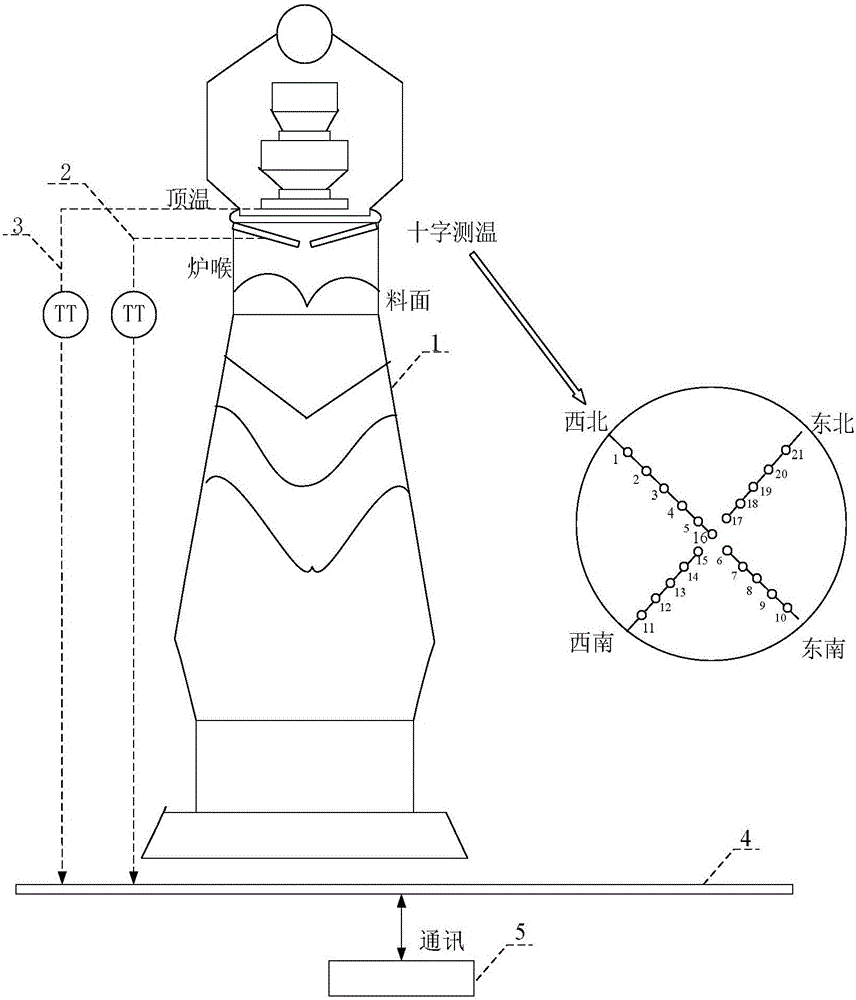
[0095] like figure 1 As shown, the cross temperature measuring device and the top temperature measuring device are respectively installed at the corresponding positions of the furnace throat and the furnace roof. The data collector is connected to the temperature measuring system, and connected to the computer system running the M-SVR estimation software through the communication bus.

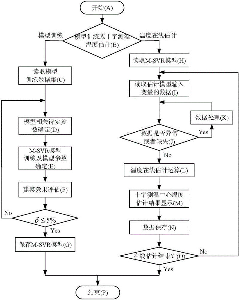
[0096] The realization method of the present invention includes (1) determination of model input variables (2) determination of modeling strategy (3) determination of model training samples (4) training and use of M-SVR estimation model.

[0097] For convenience of description, the symbols and terms used in the present invention are defined as follows:

[0098] The temperature of temperature measurement point 3 at the current sampling time x 1 (t)(°C);

[0099] Temperature measurement point 4 at the current sampling time x 2 (t)(°C);

[0100] Temperature measurement point 8 temperature at ...


PUM


Abstract

The invention discloses a central temperature estimation method of a crossed temperature measurement device of a blast furnace, belongs to the field of the automation control of blast furnace smelting, and particularly relates to a central temperature estimation method of the crossed temperature measurement device of the blast furnace on the basis of an M-SVR (Multi-output Support Vector Regression). The central temperature estimation method constructs a central temperature estimation model of crossed temperature measurement, wherein the central temperature estimation model is provided with an output self-feedback structure, considers input data of a previous moment and carries out on-line estimation on the temperature of five temperature measurement points of a crossed temperature measurement center. When the central temperature point of the crossed temperature measurement can not be normally measured, operation personnel can estimate the distribution of gas flow in the furnace according to the temperature estimation value of the model, timely regulates a burden distribution matrix and guarantee the stable direct motion of the blast furnace. The central temperature estimation method comprises the following steps: (1) selecting a model input variable; (2) determining a modeling strategy; and (3) determining a model training sample.

Description

technical field [0001] The invention belongs to the field of automatic control of blast furnace smelting, in particular to a method for estimating the center temperature of a blast furnace cross temperature measuring device based on a multi-output support vector regression machine (M-SVR). Background technique [0002] As a widely used blast furnace top temperature monitoring device, the cross temperature measurement is an important indicator of the blast furnace's stable and smooth operation. Accurately monitoring the temperature of the cross temperature measurement, estimating the gas flow distribution in the furnace, and adjusting the material distribution system in time can assist the blast furnace to run smoothly and achieve high-yield and high-efficiency effects. However, the temperature in the center of the blast furnace is too high, resulting in a short service life of the sensors of the cross temperature measuring device, especially the five temperature measuring po...

Claims


Application Information

Patent Timeline
IPC IPC(8): G06F19/00C21B5/00C21B7/24
CPCC21B5/006C21B7/24G16Z99/00
Inventor 周平尤磊王宏
Owner NORTHEASTERN UNIV
Learn More